En-5
Fig. 11
Fig. 9
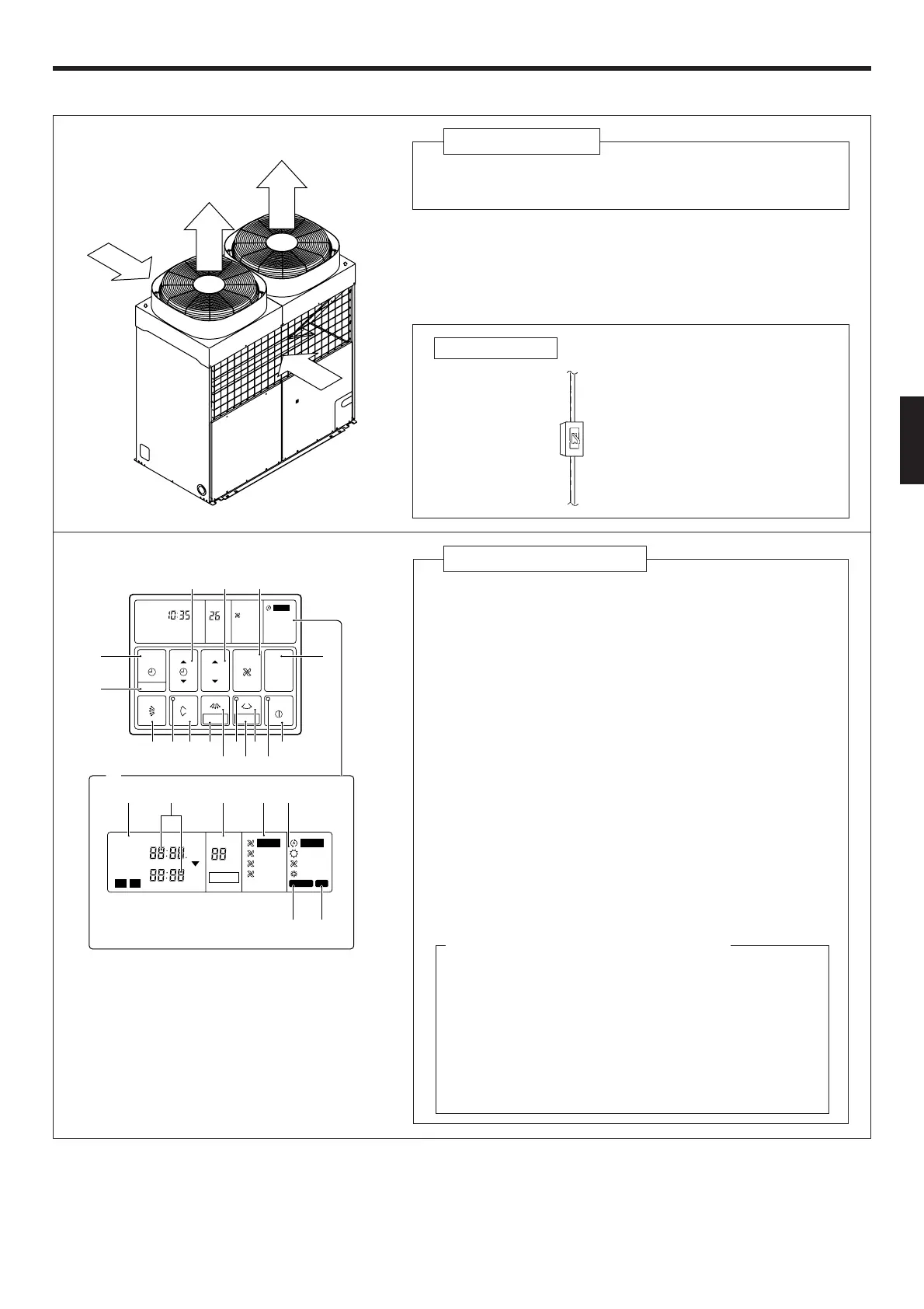
Fig. 9 Outdoor Unit
Y Intake Port
Z Outlet Port
This breaker is installed during
the electrical installation.
Electrical Breaker
Fig. 10
For explanatory purposes, the figure showing the re-
mote controller display shows all possible displays.
The actual display shows only that area that is being
adjusted or used.
Fig. 12 Display
Fig. 11 Remote Controller
[ START/STOP Button
\ Operation Lamp
] HORIZONTAL SWING Button
_ DAY OFF Button
a HORIZONTAL SWING Lamp
b
HORIZONTAL AIR FLOW DIRECTION SET Button
c SET Button
d VERTICAL SWING Button
e VERTICAL SWING Lamp
f
VERTICAL AIR FLOW DIRECTION SET Button
g CLOCK ADJUST Button
h TIMER MODE Button
i SET TIME Button
j SET TEMP./DAY Button
k FAN CONTROL Button
l MASTER CONTROL Button
m Remote Controller Display (Fig. 12)
n Timer Mode Display
o Clock Display (CLOCK/TIMER)
p Set Temperature Display (TEMP.)
q Fan Speed Display
r Operation Mode Display
s DEFROST Display
t TEST Display
°C
NON STOP
CLOCK
TEMP.
TIMER
MODE
SET
START/STOP
CLOCK ADJUST
SET TIME TEMP./DAY FAN
CONTROL
MASTER
CONTROL
HIGH
AUTO
DAY OFF
°C
NON STOP
CLOCK
TIMER
NEXT DAY
DAY
TEMP.
OFFON
TIMER
WEEKLY
AUTO
OFF
ON
OFF
ON
DAY OFF
21
HIGH
MED
LOW
AUTO
HEAT
FAN
COOL
DEFROST TEST
f d c [
b
]e
_
a
\
i
h
l
g
j k
s
t
n
m
opqr
*
Y
Z
Z
Y
Instructions relating to heating(*) are applicable only to “HEAT & COOL MODEL” (Reverse Cycle).