En-14
6. 5. 2. Wiring rules
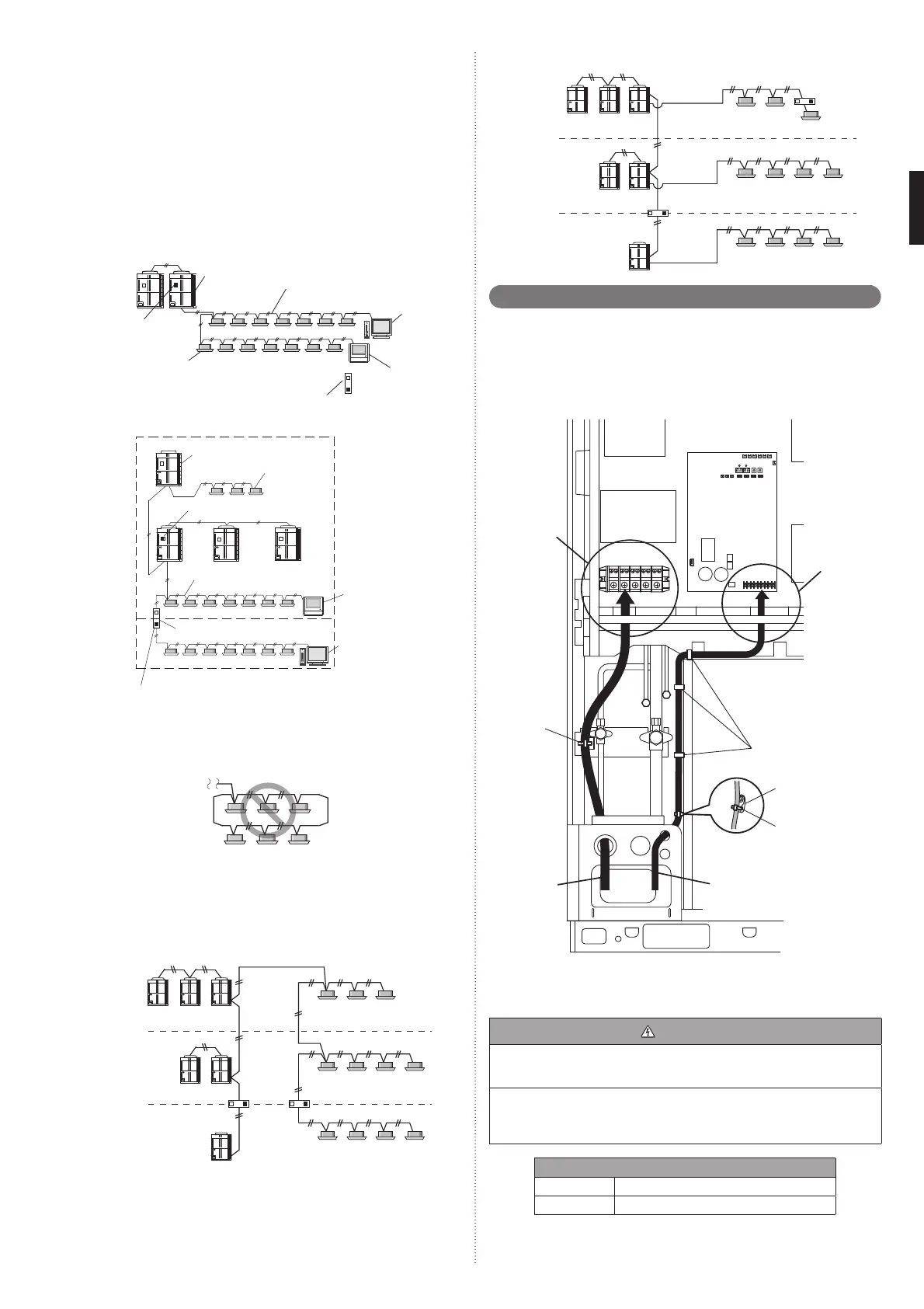
(1) Total length of transmission cable
Total transmission line length : Max. 3,600 m
EF + EG + GH + HJ + HK + KL < 3,600 m (Fig.2)
In the following cases , Signal Amplifi er is required.
1
When the total length of the transmission line exceeded 500 m.
AB + BC + BD > 500 m (Fig.1)
2
When the total number of units* is over 64.
3
Transmission line length between each unit* ≥ 400 m
(2) Length of transmission cable between 1 network segment (NS)
EF + EG + GH + HJ + HK ≤ 500 m (Fig.2)
KL ≤ 400 m (Fig.2)
(3) Length of transmission cable between outdoor units in a refrigerant system
MN ≤ 18 m
NP ≤ 18 m
Fig. 1
Transmission line
Outdoor unit
Indoor unit
System
Controller
Touch
Panel
Controller
Terminal
resistor
When AB + BC + BD > 500 m :
Signal Amplifi er is required.
A
B
C
D
Fig. 2
Outdoor unit
Indoor unit
Signal Amplifi er
System
Controller
Touch
Panel
Controller
Transmission line
Terminal resistor
Terminal resistor
NS 1
NS 2
F
H
L
G
K
J
E
P
M
N
NOTE)
Unit* means indoor unit, outdoor unit, Touch Panel Controller and System Controller,
Signal Amplifi er, single split adaptor, Network Convertor etc..
Do not use loop wiring. This may lead to parts damage and erroneous operation.
6. 5. 3. Enabling/Disabling automatic address setting
You can enable/disable automatic address setting for the indoor unit and the signal
amplifi er.
To enable automatic address setting for the indoor unit, connect the indoor unit to
outdoor units under the same refrigerant system.
Example : Disable Automatic Address setting
Refrigerant
system 1
Refrigerant
system 2
Refrigerant
system 3
Transmission line
Transmission line
Transmission line
Example : Enable Automatic Address setting
Refrigerant
system 1
Refrigerant
system 2
Refrigerant
system 3
Transmission line
Transmission line
Transmission line
6. 6. Wiring procedure
• Remove the cover of the electrical compartment and follow the terminal plate to con-
nect the electric cables to the terminal.
• After connecting the cables, secure them with the cable ties.
• Connect the cables without applying excessive tension.
Cable routing
Secure with a cable tie as shown in the fi gure below.
Connecting the
power supply
cable
Connecting the
transmission
cable
Power supply
cable routing
Transmission cable routing
Cable tie *
(Accessory)
Cable clip
Cable guide
Cable tie
(Accessory)
* Tighten the cable tie fi rmly so that pulling force does not propagate to the terminal
connection even if force of 100N is applied to the cable.
Connecting cables to the terminals
WARNING
Use ring terminals and tighten the terminal screws to the specifi ed torques, other-
wise, abnormal overheating may be produced and possibly cause heavy damage
inside the unit.
Be sure fi ll the holes of power supply cable and transmission cable with putty (fi eld
supply).
If small animals such as insects enter the electrical component box, a short circuit
may be caused.
Tightening torque
M3 screw 0.5 to 0.6 N·m (5 to 6 kgf·cm)
M8 screw 5.0 to 7.0 N·m (50 to 70 kgf·cm)
9378945180-02_IM.indb 149378945180-02_IM.indb 14 2014/11/10 19:39:572014/11/10 19:39:57
 Loading...


