En-12
In case of connected 3 outdoor unitFig.
GOOD
Sub
breaker
Outdoor unit power supply cable
400 V 3ø
50 Hz
Main
breaker
Example of bad breaker wiring(3)
PROHIBITED
400 V 3ø
50 Hz
Outdoor unit
Power supply cable
PROHIBITED: crossover
power supply wiring prohibited
Breaker
PROHIBITED: install a
breaker for each outdoor unit
Transmission line6. 5.
CAUTION
Caution when wiring cable•
When stripping off the coating of lead wire, always use the exclusive tool such as
a wire stripper. If there is no exclusive tool available necessarily, carefully strip the
coating by a cutter etc. so that the conductive wire is not damaged.
If it is damaged, it may lead to an open circuit and a communication error.
Pay attention to the following points while attaching wires on the terminal board.•
Do not attach 2 wires on one side.
Do not twist wires.
Do not cross the wires.
Do not shorted at edge at root.
PROHIBITED
GOOD
PROHIBITED
PROHIBITED PROHIBITED
GOOD
2pcs at one side
Shorted at edge
Wires twisted
Shorted at root
1 wire
2 wires
Transmission wiring specifi cations6. 5. 1.
Follow the specifi cations below for the transmission cable.
Use Size Wire type Remarks
Transmission
cable
0.33mm
2
22AWG LEVEL 4 (NEMA)
non-polar 2core, twisted pair
solid core diameter 0.65mm
LONWORKS
®
com-
patible cable
Wiring rules6. 5. 2.
(1) Total length of transmission cable
Total transmission line length : Max. 3,600 m
EF + EG + GH + HJ + HK + KL < 3,600 m (Fig.2)
In the following cases , Signal Amplifi er is required.
①
When the total length of the transmission line exceeded 500 m.
AB + BC + BD > 500 m (Fig.1)
②
When the total number of units* is over 64.
③
Transmission line length between each unit* ≥
400m
(2) Length of transmission cable between 1 network segment (NS)
EF + EG + GH + HJ + HK ≤ 500 m (Fig.2)
KL ≤ 400 m (Fig.2)
(3) Length of transmission cable between outdoor units in a refrigerant system
MN ≤ 18 m
NP ≤ 18 m
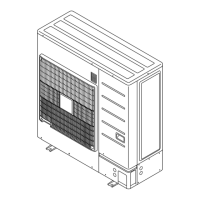
< Left view >
< Front view >
(Unit: mm)
Ø 50
Ø 34.5
Ø 43.7
Ø 22.2
Ø 50
Ø 34.5
Ø 43.7
Ø 22.2
Selecting power supply cable and breaker6. 4.
CAUTION
Obtain the distribution network operator's agreement about the power capacity of
the power supply system, specifi cation of the cable and the harmonic current, and
etc. when you connect the outdoor unit with the power supply.
Regulation of wire size and circuit breaker differs from each locality, please refer in
accordance with local rules.
Refer to the table for the wiring and breaker specifi cations of each installation condition
.
Selecting power supply cable and breaker when connecting 1 outdoor unit(1)
MODEL
Breaker (Time delay fuse or circuit capacity)
Fuse capacity (A) Leakage current
AJ
A72LALH 30
100mA
0.1sec or less
AJ
A90LALH 30
AJ
108LALH 50
AJ
126LALH 50
AJ
144LALH 50
MODEL
Outdoor unit power supply cable
Power supply
cable (mm
2
)
Ground wire (mm
2
)
Critical wiring
length (m)
AJ
A72LALH 4 4 30
AJ
A90LALH 4 4 30
AJ
108LALH 10 6 42
AJ
126LALH 10 6 42
AJ
144LALH 10 6 42
These values are recommended data. 1)
Specifi cation: Use conformed cord with Type 60245 IEC66 2)
Max. wire length: Set a length so that the voltage drop is less than 2%. Increase 3)
the wire diameter when the wire length is long.
In case of connected outdoor unitFig.
GOOD
Transmission cable
Remote controller cable
Breaker
400 V 3ø 50 Hz
Breaker
230 V 1ø 50 Hz
Outdoor unit
Power supply cable
Indoor unit
Power supply cable
Selecting main breaker and main power supply cable when connecting multiple (2)
outdoor units
Main breaker: Main breaker ≥ Total Sub breaker
(Refer to the table in item (1) for the
sub breaker capacity)
9378945104-01_IM.indb Sec1:129378945104-01_IM.indb Sec1:12 2013-3-12 14:08:242013-3-12 14:08:24
 Loading...
