En-6
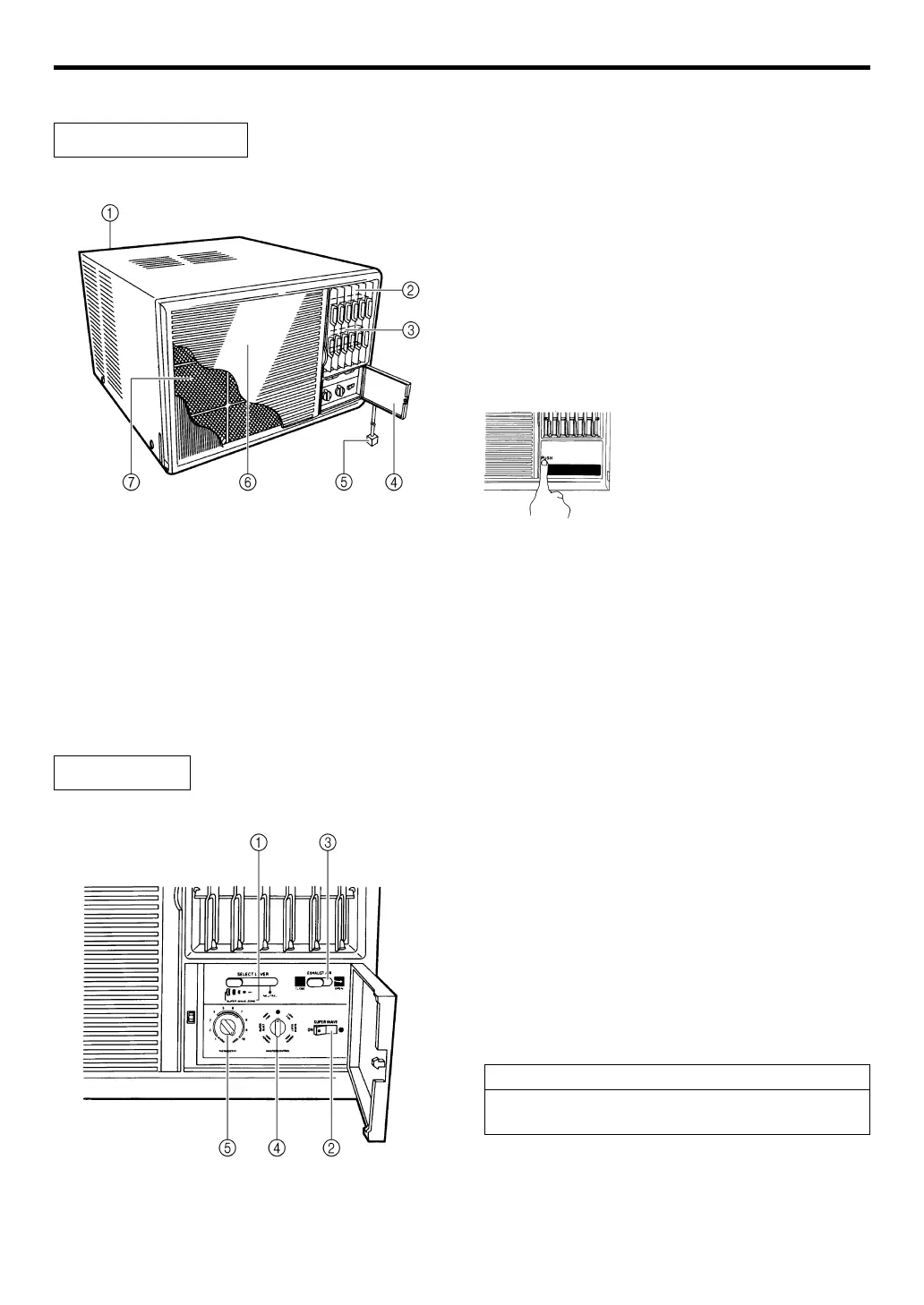
NAME AND FUNCTION OF PARTS
For details of operation, see the pages indicated by the ☞ mark.
Air Conditioner Unit
1 Drain Boat or Drain Tube
(At the bottom of the back side)
Moisture condensed from the air during Cooling
is drained here.
2 Right-Left Airflow-direction Louvres
(☞ P. 10)
Control airflow in the horizontal (right-left) direction.
This can also be swept.
3 Up-Down Airflow-direction Louvres
(Behind Airflow-direction Louvres)
(☞ P. 10)
Control airflow in the vertical (up-down) direction.
4 Control Panel Cover
5 Power Supply Plug
6 Air Intake Grille
Air is taken in here.
7 Air Filter (☞ P. 13)
Removes all dirt and dust from the air.
Control Panel
1 SELECT Lever
NEUTRAL: When changing the airflow by manual ope-
ration.
SUPER WAVE ZONE:
When SUPER WAVE is operated, adjust to
the desired air flow direction (☞ P. 11).
2 SUPER WAVE Switch
) (OFF): When the air conditioner is operated by one
direction airflow.
ON: When taking out the airflow in the widerange.
3 EXHAUST AIR Lever
CLOSE: Ventilation circulates through indoor air,
without being carried out.
OPEN: Cigarette smoke and smell are exhausted to
outside a room.
4 MASTER CONTROL Switch (☞ P. 7, 8)
5 THERMOSTAT Control Switch (☞ P. 9 )
When opening and closing the
control panel cover, press the
position of “PUSH” by your finger.
Note:
Cooling effect will be reduced when operating EXHAUST
AIR “OPEN”.