En-13
6.2. Indoor unit pipe connections
CAUTION
For details, refer to the Installation Instruction Sheet of each part.
Separation tube
A:
Outdoor unit or Refrigerant
branch kit
B:
Indoor unit or Refrigerant
branch kit
A
B
A
B
B
A
± 15°
GOOD GOOD
Horizontal
Vertical
Horizontal line
or
PROHIBITED
Header
C
H
1
α
1
β
1
D
H
2
α
2
β2
GOOD
GOOD
Horizontal line
Horizontal line
View
D
View C
Horizontal line
Vertical line
Gas pipe
Liquid pipe
Outdoor
unit side
Outdoor
unit side
H
1
= to 3/8 in
(0 to 10 mm)
H
2
= to 3/8 in
(0 to 10 mm)
(α
1
: 0° to 1°)
β
1
: -10° to 10°
(α
2
: 0° to 1°)
β
2
: -10° to 10°
PROHIBITED
CAUTION
Do not connect a separation tube after a header.
Leave the distance 2 ft (0.5 m) or more for straight part to branch tube and header.
To indoor unit
To indoor unit
To indoor unit
Main pipe
Main pipe
2 ft (0.5 m) or more
2 ft (0.5 m) or more
To indoor unit
Separation tube
Header
To indoor unit
2 ft (0.5 m) or more
2 ft (0.5 m) or more
To indoor unit
Separation tube
Header
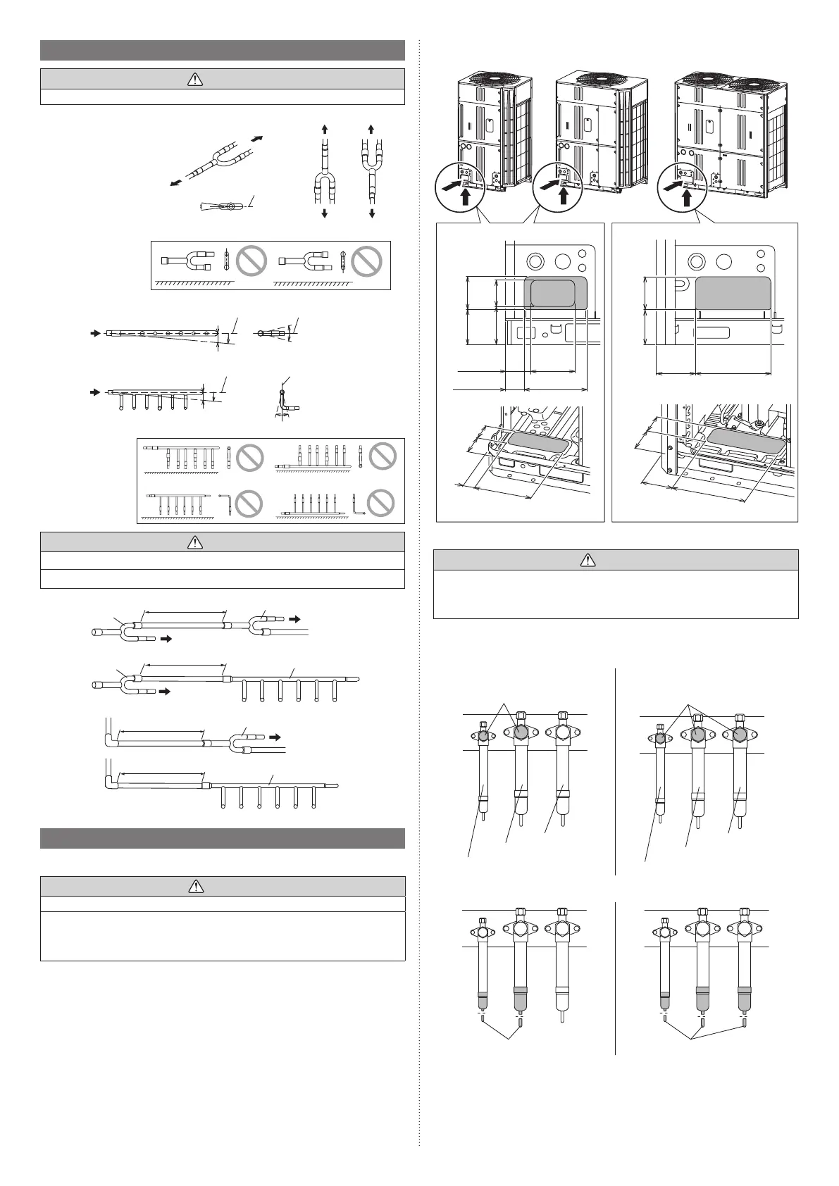
6.3. Piping method
6.3.1 Opening the knockout hole
CAUTION
Be careful to prevent panel deformation or damaged while opening the knockout hole.
To prevent cutting of the wiring after the knockout hole was opened, remove the burrs
along the edge.
In addition, to prevent rusting, painting the edge with rust preventive paint is recom-
mended.
The piping can be connected from 2 directions; the front or the bottom.
(Knockout holes are provided so that the piping can be connected from 2 different direc-
tions.)
Knockout position and detail
4-15/16
(125)
7-1/16 (179)
7-3/4
(197)
1-5/8
(42)
3-1/8
(80)
3-1/4
(82)
8-1/2 (216)
4-7/16
(113)
4-5/16
(110)
3-1/4
(83)
3-1/8
(80)
8-11/16
(220)
2-7/8 (73)
2-15/16
(75)
3-3/4
(95)
3-3/4
(95)
3-15/16
(100)
4-5/16
(110)
3-15/16
(100)
2-1/16 (53)
AOUA120AOUA72/96 AOUA144/168/192
[Unit: in (mm)[Unit: in (mm)
6.3.2 Removing the pinch pipe
WARNING
Remove the pinch pipe only when the internal gas is completely drained as shown on
the below instructions.
If gas still remains inside, the piping may crack if you melt the brazing filler metal of the
junction area with a burner.
Before connecting the piping, remove the pinch pipe in accordance with the following
instructions:
(1) Verify that the liquid side and gas side 3-way valves are closed.
For Heat Pump system For Heat Recovery system
3-way valve
For liquid pipe
For gas pipe
Do not use
For liquid pipe
For discharge gas pipe
For suction gas pipe
3-way valve
(2) Cut the end of the liquid side and gas side pinch pipe and vent the gas inside the
pinch pipe.
End of pinch pipe End of pinch pipe
9378945722-05_IM_L3.indb 139378945722-05_IM_L3.indb 13 2023/3/24 9:23:492023/3/24 9:23:49