En-19
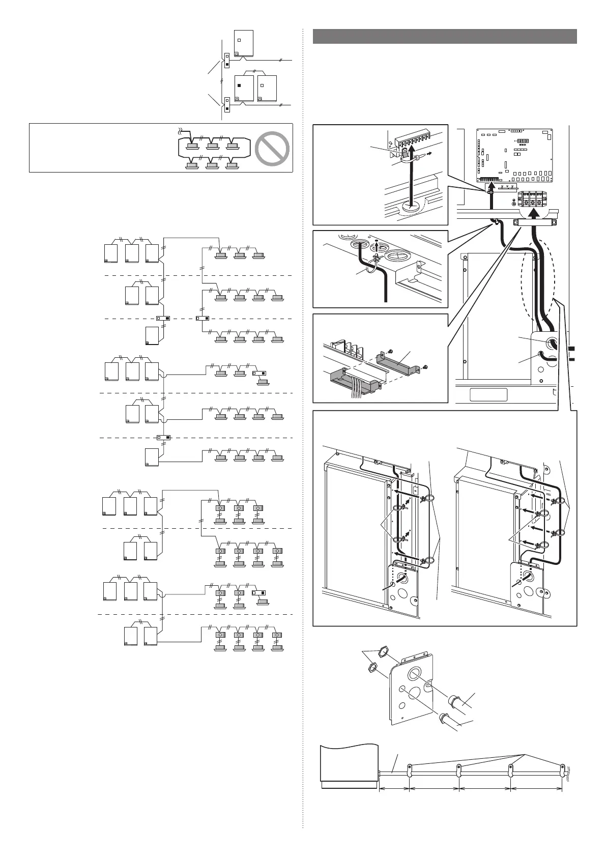
• If there are more than 321 units (*1) within
the network system, a Signal amplifier
(with the filter mode: on) must be installed
between the primary outdoor units. See
the Signal amplifier installation manual
and Design & Technical manual for more
information.
*1: Unit* means indoor unit, outdoor unit,
Touch panel controller and System
controller, Signal amplifier, single split
adaptor, Network convertor etc.
Signal amplifier
(Filter mode: on)
Do not use loop wiring. This may lead to parts
damage and erroneous operation.
7.5.4 Enabling/Disabling automatic address setting
You can enable/disable automatic address setting for the indoor unit, RB unit (only for
Heat Recovery system) and the Signal amplifier.
To enable automatic address setting for the indoor unit, connect the indoor unit to outdoor
units under the same refrigerant system.
Example of Heat Pump system
Disable auto-
matic address
setting
Refrigerant system 1
Refrigerant system 2
Refrigerant
system 3
Transmission line
Transmission line
Transmission line
Enable auto-
matic address
setting
Refrigerant
system 3
Refrigerant system 1
Refrigerant system 2
Transmission line
Transmission line
Transmission line
Example of Heat Recovery system
Disable Auto-
matic Address
setting
Refrigerant system 1
Refrigerant system 2
Transmission line
Transmission line
Enable Auto-
matic Address
setting
Refrigerant system 1
Refrigerant system 2
Transmission line
Transmission line
7.6. Wiring procedure
• Remove the cover of the electrical compartment and follow the terminal plate to connect
the electric cables to the terminal.
• After connecting the cables, secure them with the cable ties.
• Connect the cables without applying excessive tension.
7.6.1 Cable routing
Secure with the cable clamp and cable ties as shown in the following figure.
* Tighten the cable clamp and cable tie firmly so that pulling force does not propagate to
the terminal connection even if force of 100 N is applied to the cable.
AOUA72/96/120 AOUA144/168/192
Cable tie (accessory)
Power supply
cable routing
Transmission
cable routing
Cable clamp
Fix the transmission
cables to cable clip
with cable tie (ac-
cessory).
Pass the power supply cables through
the clamp and secure these.
Push mount cable
tie (accessory)
Fix the cables with push mount cable tie (accessory). The fixed position and number
vary depending on the model.
Cable clip
Push mount cable
tie (white) (acces-
sory)
Black: for
power supply
cable
White: for
transmission
cable
White: for trans-
mission cable
Black: for power
supply cable
7.6.2 Attaching the conduit
Lock nuts
Conduit (power supply cable)
Conduit (transmission cable)
• Fix the conduit with the supporters as shown below.
Outdoor unit
Conduit (power supply cable) Supporter
[Unit : in (mm)] 30 (756)
or less
54 (1,361)
or less
54 (1,361)
or less
54 (1,361)
or less
9378945722-05_IM_L3.indb 199378945722-05_IM_L3.indb 19 2023/3/24 9:23:492023/3/24 9:23:49