En-20
7.6.3 Connecting cables to the terminals
WARNING
Use ring terminals and tighten the terminal screws to the specified torques, otherwise,
abnormal overheating may be produced and possibly cause heavy damage inside the
unit.
Be sure fill the holes of power supply cable and transmission cable with duct seal (locally
purchased).
If small animals such as insects enter the electrical component box, a short circuit may
be caused.
Tightening torque
M3 screw 4.4 to 5.3 lbf·in (0.5 to 0.6 N·m)
M8 screw 44.3 to 62.0 lbf·in (5.0 to 7.0 N·m)
How to connect wiring to the terminal
Caution when wiring cable
(1) Use ring terminals with insulating sleeves as shown in the figure to connect to the
terminal block.
(2) Securely clamp the ring terminals to the cables using an appropriate tool so that
the cables do not come loose.
(3) Use the specified cables, connect them securely, and fasten them so that there is
no stress placed on the terminals.
(4) Use an appropriate screwdriver to tighten the terminal screws. Do not use a screw-
driver that is too small, otherwise, the screw heads may be damaged and prevent
the screws from being properly tightened.
(5) Do not tighten the terminal screws too much, otherwise, the screws may break.
(6) See the table below for the terminal screw tightening torques.
Strip 3/8 in
(10 mm)
Cable
Screw with
special washer
Ring terminal
Terminal block
Ring terminal
Sleeve
Screw with
special washer
Ring terminal
Cable
7.6.4 Connecting the power supply cable
* Use a ring terminal to connect the electric cables to the power supply terminal block.
L1 L2 L3
Ring terminal: M8
2-3/8 to 2-3/4 in
(60 to 70 mm)
Ground (Earth) cable
7.6.5 Connecting the transmission cable
Shielding the transmission cable
Connect both ends of the shielded
wire of the transmission cable to
the ground (earth) terminal of the
equipment or to the ground (earth)
screw near the terminal.
Be sure to use one side of a
twisted-pair cable when using
transmission cable with 2 sets of
twisted-pair cables.
Wind with insulation tape to prevent short circuit
Use one side
of the twisted
pair cable
Connect both ends of shielded
wire to ground (earth).
5/16 to 3/8 in
(8 to 10 mm)
1-9/16 in (40 mm)
or more
To other refrigerant system outdoor unit
To multiple connected
outdoor unit
To indoor unit
Cable tie (accessory)
Cable clip
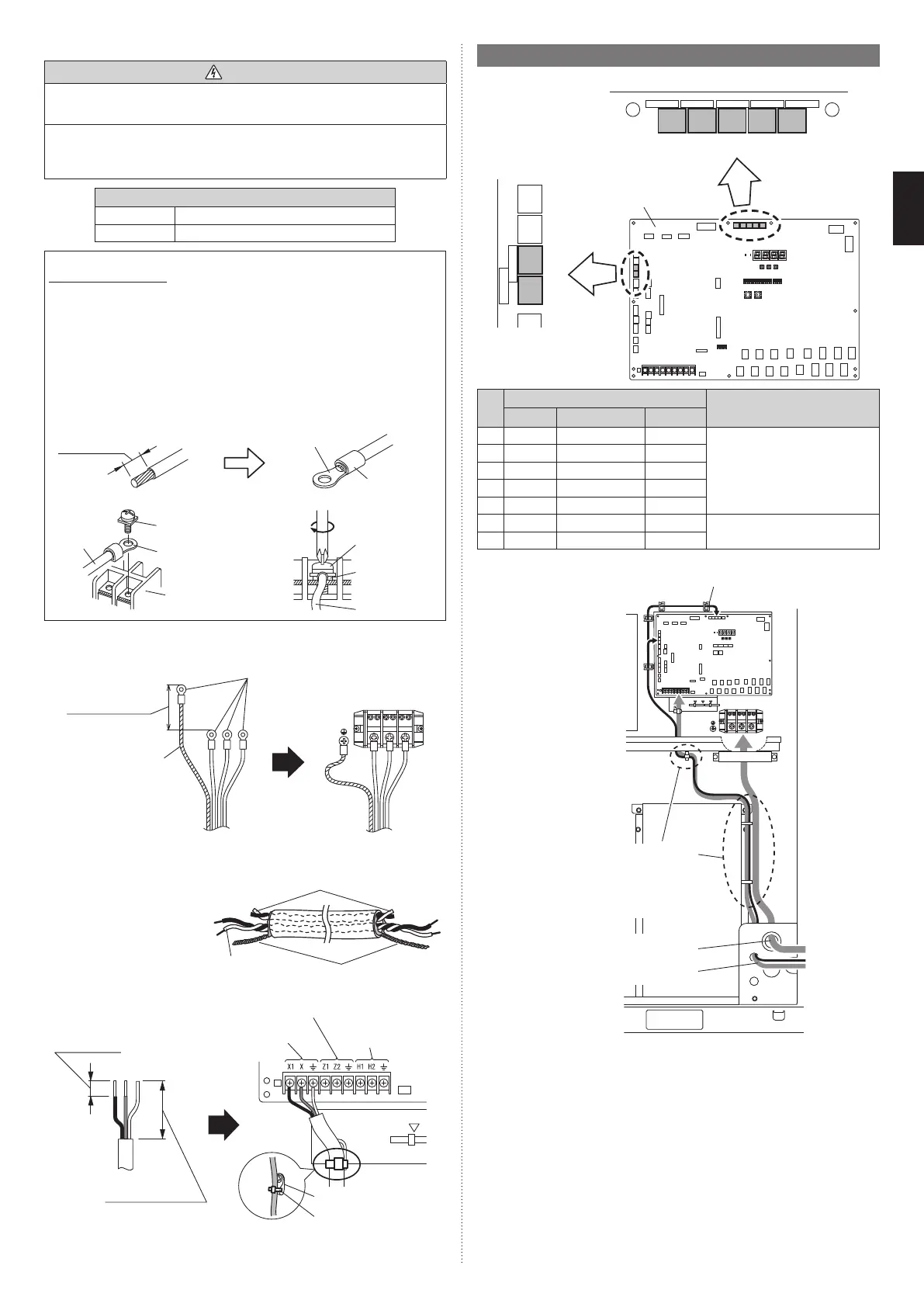
7.7. Optional parts wiring
7.7.1 Terminal positions
EXT. IN. 1
CN131
EXT. OUT. 2
CN137
EXT. OUT. 1
CN136
EXT. IN. 2
CN132
EXT. IN. 3
CN133
EXT. IN. 4
CN134
PULSE. IN
CN135
(1) (2) (3) (4) (5)
(6)
(7)
Main PC board
Terminal
Application
Number Name Color
(1) CN131 EXT. IN. 1 Yellow For external input
(2) CN132 EXT. IN. 2 Green
(3) CN133 EXT. IN. 3 White
(4) CN134 EXT. IN. 4 Red
(5) CN135 PULSE. IN Orange
(6) CN136 EXT. OUT. 1 Black For external output
(7) CN137 EXT. OUT. 2 Blue
7.7.2 Optional parts Cable routing
Power supply cable routing
Transmission cable routing
Cable guide
The optional parts cables are
bound with the push mount
cable ties (accessories)
together with the transmission
cable. Refer to “7.6.1 Cable
routing”.
7.7.3 External input terminal
• Setting to low noise mode, outdoor unit operation peak control setting, emergency/batch
stop and electricity meter pulse are possible from the outside.
• Except for wattmeter pulse reception (CN135) among external input terminals, only the
primary unit is effective.
Wiring method and specifications
* A twisted pair cable (0.33 mm² (22AWG)) should be used. Maximum length of cable is
150 m.
* Use an external input and output cable with appropriate external dimension, depending
on the number of cables to be installed
* For each input, pin No. 1 is of positive polarity and pin No. 2 is of ground level.
9378945722-05_IM_L3.indb 209378945722-05_IM_L3.indb 20 2023/3/24 9:23:502023/3/24 9:23:50