En-18
7.5.1 Transmission wiring specifications
Follow the specifications below for the transmission cable.
Use Size Cable type Remarks
Transmission cable
22AWG
(0.33 mm²)
LEVEL 4 (NEMA) nonpolar
2-core, twisted pair solid core
diameter 0.026 in (0.65 mm)
LONWORKS ®
compatible cable
Twisted pair with shielded type.
Use the shielded wire specified and always ground it both ends.
7.5.2 Wiring rules for Heat Pump system
(1) Total length of transmission cable
Total transmission line length : maximum 11,811 ft (3,600 m)
EF + EG + GH + HJ + HK + KL < 11,811 ft (3,600 m) (Fig. 2)
In the following cases , Signal amplifier is required.
1) When the total length of the transmission line exceeded 1,640 ft (500 m).
AB + BC + BD > 1,640 ft (500 m) (Fig.1)
2) When the total number of units* is over 64.
3) Transmission line length between each unit* ≥ 1,312 ft (400 m)
(2) Length of transmission cable between 1 network segment (NS)
EF + EG + GH + HJ + HK ≤ 1,640 ft (500 m) (Fig.2)
KL ≤ 1,312 ft (400 m) (Fig.2)
(3) Length of transmission cable between outdoor units in a refrigerant system
MN ≤ 59 ft (18 m)
NP ≤ 59 ft (18 m)
Fig. 1
A
BC
D
Transmission line
Outdoor unit
Indoor unit
System
controller
Touch panel
controller
Terminal
resistor
When AB + BC + BD > 1,640 ft (500 m):
Signal amplifier is required.
Fig. 2
E
F
MN P
G
H
K
J
L
NS 2
NS 1
Outdoor unit
Indoor unit
Signal amplifier
System
controller
Touch panel
controller
Transmission line
Terminal resistor
Terminal resistor
Do not use loop wiring. This may lead to parts
damage and erroneous operation.
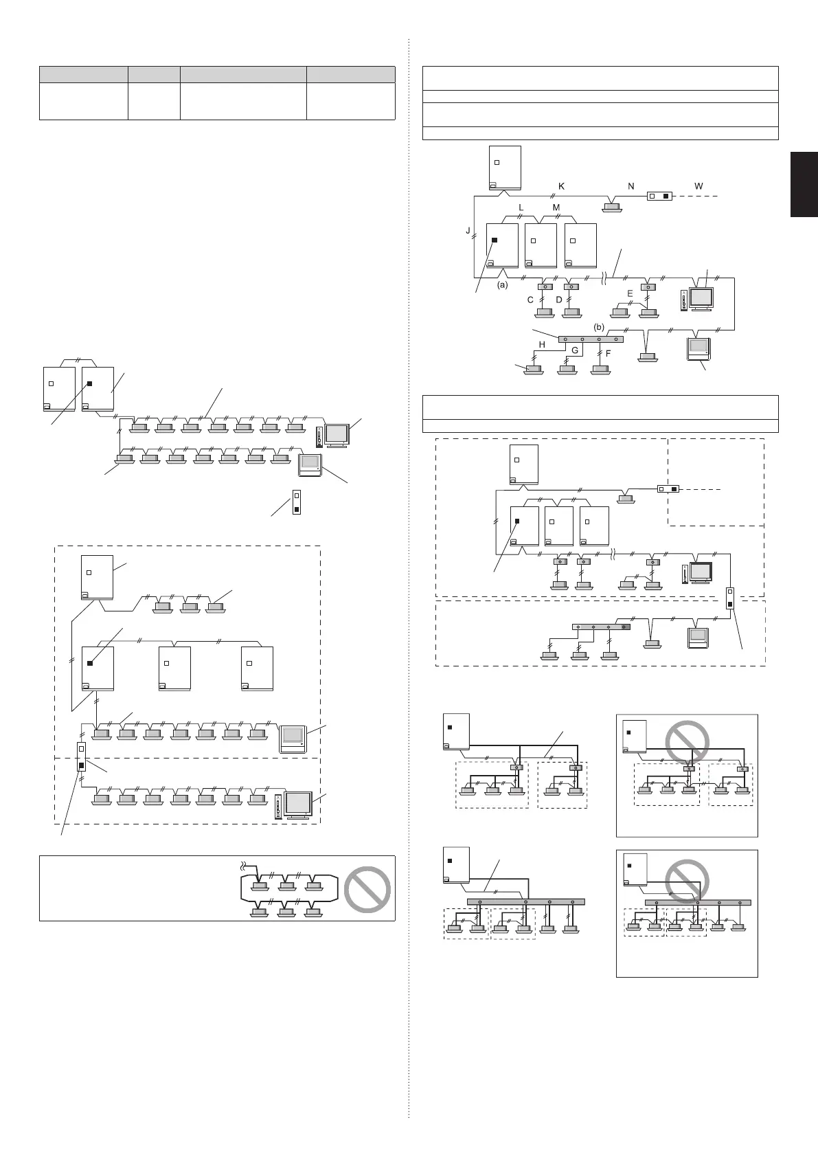
7.5.3 Wiring rules for Heat Recovery system
(1) Basic wiring rules
Total transmission line length: maximum 11,811 ft (3,600 m)
(A + C + D + E + F + G + H + J + K + N + W ≤ 11,811 ft (3,600 m))
Transmission line length between each unit: maximum 1,312 ft (400 m)
Transmission line length between outdoor units in a refrigerant system: maximum 18 m
(L ≤ 59 ft (18 m), M ≤ 59 ft (18 m))
Be sure to set 1 terminal resistor in a network segment.
Indoor unit
Transmission line
RB unit
Terminal resistor
System controller
Touch panel controller
A (a to b)
(2) In the following cases, Signal amplifier is required.
When the total length of the transmission line exceeded 1,640 ft (500 m)
(A + C + D + E + F + G + H + J + K + N ≥ 1,640 ft (500 m))
When the total number of units is over 64.
C
NS 1
F
H
G
K
J
E
WN
NS 2
NS 3
D
(a)
(b)
(c)
* P + C + D + E + J + K + N ≤ 1,640 ft (500 m), Q + F + G + H ≤ 1,640 ft (500 m)
Signal amplifier
Terminal resistor
P (a to c)
Q (c to b)
The transmission cable connects indoor units belonging to the same RB group. The trans-
mission cable cannot be used to connect indoor units belonging to different RB groups.
Transmission line
Refrigerant pipe
RB group 1
RB group 1
RB group 2
RB group 2
GOOD
PROHIBITED
RB unit
(multi type)
Transmission line
Refrigerant pipe
RB unit
(multi type)
GOOD
PROHIBITED
RB
group 1
RB
group 2
RB
group 3,4
RB
group 3,4
RB
group 1
RB
group 2
9378945722-05_IM_L3.indb 189378945722-05_IM_L3.indb 18 2023/3/24 9:23:492023/3/24 9:23:49