Serial Signal Diagnosis
[Check Point] Check and find out if the cause is at Indoor unit or Outdoor unit.
* Remove the side cover of Outdoor unit for testing the Outdoor unit connection terminals with a meter.
* Turn on the power and press [TEST] button of Remote control.
[Checking Flow Chart]
[Check Indoor Unit]
CAUTION: Do not touch the terminals or electrical components to avoid electric shock.
Connecting cable wiring defect
In correct wiring
Main PCB defective
NO
YES
Measure the voltage between terminals N-3 on the
Outdoor unit terminal plate.
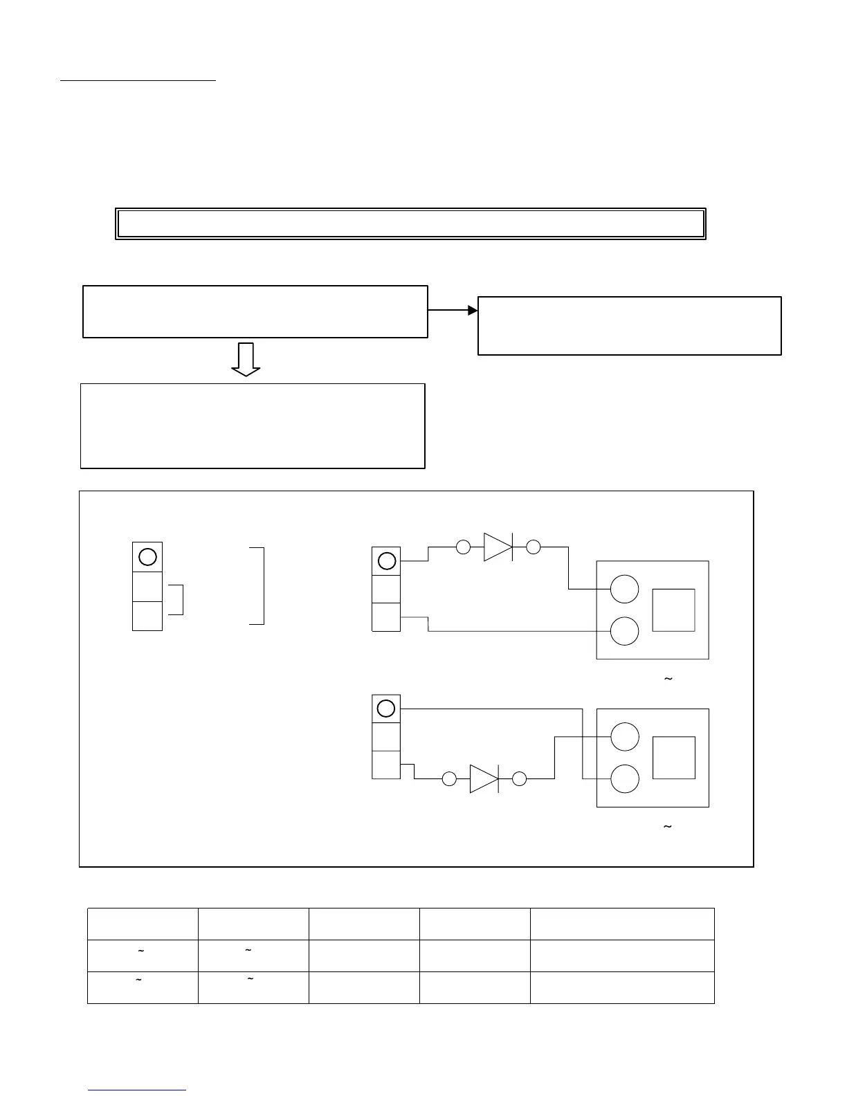
Refer to Fig.1 for Measuring Method.
Judge the result based on Table 1.
L
N
+
Measurement method 1
Diode
(Dielectric voltage : Higher than 600V)
Range DC
(Normal : DC30 60V)
Red
Black
White
+
Range DC
(Normal : DC30 60V)
Red
Black
White
L
N
Fig.1 Selial Signal Measuring Method
Measurement 1 Measurement 2 Indoor unit Outdoor unit
Defective point
voltage value voltage value trouble display operation
0 5V
30 60 V Display No operation Indoor unit control PCB defective
30 60V 0 5V Display No operation Outdoor unit fuse open (input)
Inverter defective
Table 1: Judgement table
L
N
Outdoor unit terminal
plate
Power supply
AC220V/230V
Black
White
Serial
signals
-
-
3
3
3
Red
Measurement method 2
07-08