EasyManua.ls Logo

Fujitsu AOYA18LACL User Manual

Fujitsu AOYA18LACL
36 pages
To Next Page IconTo Next Page
Page #1 background imageLoading...
Page #1 background image
CONTENTS
SPECIFICATIONS
. . . . . . . . . . . . . . . . . . .
1
OUTLINE AND DIMENSIONS
. . . . . . . . .
2
REFRIGERANT SYSTEM DIAGRAM
. . .
5
ERROR DISPLAY
. . . . . . . . . . . . . . . . . .
7
CIRCUIT DIAGRAM
. . . . . . . . . . . . . . . . .
6
PCB CIRCUIT DIAGRAM
. . . . . . . . . . . . .
17
PARTS (indoor unit)
. . . . . . . . . . . . . . . .
20
PARTS (outdoor unit)
. . . . . . . . . . . . . . .
30
ACCESSORIES
. . . . . . . . . . . . . . . . . . .
33
SPLIT TYPE
ROOM AIR CONDITIONER
FLOOR CONSOLE /
UNDER CEILING
DUAL TYPE
Indoor unit Outdoor unit
ABYF18LAT
ABYF18LAT
ABYF18LAT
ABYF18LAT
ABYF18LBT
ABYF18LBT
ABYF24LAT
ABYF24LAT
ABYF24LAT
ABYF24LAT
ABYF24LBT
ABYF24LBT
AOYA18LACL
AOYA18LALL
AOYB18LACL
AOYB18LALL
AOYA18LALL
AOYB18LALL
AOYA24LACL
AOYA24LALL
AOYB24LACL
AOYB24LALL
AOYA24LALL
AOYB24LALL
Question and Answer IconNeed help?

Do you have a question about the Fujitsu AOYA18LACL and is the answer not in the manual?

Fujitsu AOYA18LACL Specifications

General IconGeneral
BrandFujitsu
ModelAOYA18LACL
CategoryAir Conditioner
LanguageEnglish

Summary

SPECIFICATIONS

ELECTRICAL, FAN MOTOR, AND NOISE SPECIFICATIONS

Details electrical parameters, fan motor speeds, and noise levels.

COMPRESSOR, REFRIGERANT, DIMENSIONS, AND WEIGHT

Covers compressor, refrigerant, dimensions, and weight specifications.

OUTLINE AND DIMENSIONS

INDOOR UNIT DIAGRAMS

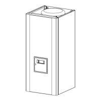
Provides dimensional drawings and measurements for the indoor unit.

OUTDOOR UNIT AOY_18LA_L DIMENSIONS

OUTDOOR UNIT AOY_24LA_L DIMENSIONS

DIMENSIONAL DRAWINGS AND MEASUREMENTS

Shows dimensional drawings and measurements for the AOY_24LA_L outdoor unit.

REFRIGERANT SYSTEM DIAGRAM

SYSTEM OVERVIEW AND PIPE DIAMETERS

Illustrates the refrigerant system and lists pipe diameters for different models.

CIRCUIT DIAGRAM

INDOOR AND OUTDOOR UNIT CIRCUITS

Electrical schematics for both indoor and outdoor units.

INDOOR PCB CIRCUIT DIAGRAM

INDOOR UNIT CONTROLLER PCB ASSEMBLY

INDOOR UNIT POWER SUPPLY PCB ASSEMBLY

INDOOR UNIT INDICATOR PCB ASSEMBLY

INDOOR UNIT CONTROL UNIT (ALT MODELS)

INDOOR UNIT CONTROLLER PCB ASSEMBLY (ALT MODELS)

INDOOR UNIT POWER SUPPLY PCB ASSEMBLY (ALT MODELS)

INDOOR UNIT INDICATOR PCB ASSEMBLY (ALT MODELS)

OUTDOOR PCB CIRCUIT DIAGRAM

INDOOR UNIT ERROR CODES

ERROR CODE DISPLAY AND CONTENTS

Explains how error codes are displayed using indicator lamps.

INDOOR UNIT ERROR CODE DESCRIPTIONS

DETAILED ERROR CODE LIST

Provides a comprehensive list of indoor unit error codes and their explanations.

WIRED REMOTE CONTROL ERROR CODES

ERROR CODE DISPLAY AND LIST

Shows how errors appear on the remote and lists specific error codes.

OUTDOOR UNIT ERROR CODES

LED ERROR INDICATORS

Describes error conditions indicated by LED blinking patterns for the outdoor unit.

Related product manuals