This document is a service manual for a Fujitsu Split Type Air Conditioner, specifically a Duct Type (50Hz) model. The indoor unit is identified as ARYG60LHTA and the outdoor unit as AOYG60LATT. The system uses R410A refrigerant.
Function Description:
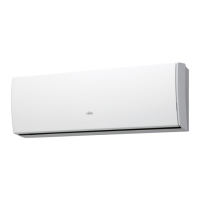
This is a split-type air conditioning system designed for both cooling and heating. The "Duct Type" designation indicates that the indoor unit is designed to be concealed within a ceiling or wall space, distributing conditioned air through a system of ducts to various rooms or areas. This allows for discreet installation and centralized climate control. The system is equipped with an inverter, which allows for variable compressor speed, leading to improved energy efficiency and more precise temperature control compared to traditional on/off systems.
Important Technical Specifications:
Electrical Data:
- Type: Cooling & Heating
- Power Source: 400 V, 50 Hz, 3 phase, 4 W
- Cooling Capacity: 15.0 kW
- Heating Capacity: 18.0 kW
- Running Current (Cooling): 6.9 A
- Running Current (Heating): 7.6 A
- Input Watts (Cooling): 4.70 kW
- Input Watts (Heating): 5.15 kW
- E.E.R. (Cooling): 3.19 kW/kW
- C.O.P. (Heating): 3.50 kW/kW
- Moisture Removal: 2.0 L/hr
- Maximum Current: 12.5 A
Noise Level:
- Indoor Unit (High/Medium/Low): 45 dB / 40 dB / 36 dB
- Outdoor Unit (Cooling/Heating): 56 dB / 58 dB
Air Circulation:
- Indoor: 3,550 m³/h
- Outdoor (Cooling): 6,900 m³/h
- Outdoor (Heating): 7,300 m³/h
Compressor and Refrigerant:
- Type: Hermetic type, Inverter, 4 poles, 3 phase, DC motor, Twin Rotary
- Discrimination: DA422A3F-29ZAD
- Weight (with oil): 23.0 kg
- Refrigerant Type: R410A
- Precharged Refrigerant: 3,450 g (for pipe length up to 30 m)
- Max Pipe Height: 30 m
- Full Charge (pipe length 30m/45m/60m/75m): 3,450 g / 4,200 g / 4,950 g / 5,700 g
- Additional Charge: 50 g/m
Fan Motor:
- Indoor Unit (Discrimination MFG-54AVN):
- High: 1,090 r.p.m. / 1,050 r.p.m.
- Medium: 900 r.p.m. / 860 r.p.m.
- Low: 780 r.p.m. / 740 r.p.m.
- Outdoor Unit (Discrimination MFE-54VVT):
- Cooling (Upper fan/Lower fan): 900 r.p.m. / 800 r.p.m.
- Heating (Upper fan/Lower fan): 900 r.p.m. / 900 r.p.m.
Dimensions (H x W x D):
- Indoor Unit: 425 x 1,250 x 490 mm
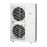
- Outdoor Unit: 1,290 x 900 x 330 mm
- Indoor Unit Drain Hose Diameter: Inside: 23.4 mm, Outside: 25.4 mm
Weight (Shipping / Net):
- Indoor Unit: 61 kg / 54 kg
- Outdoor Unit: 113 kg / 104 kg
Usage Features:
The system can be controlled via a wired remote control (UTY-RNNYN) or a simple remote control (UTY-RSNYN). An optional remote sensor (UTY-XSZX) can be installed for improved temperature sensing in the remote control area, offering more amenity space. An I.R receiver unit (UTY-LRHYM) is available for air conditioner operation and demand response display. An external control set (UTD-ECS5A) allows connection to various peripheral devices and the air conditioner PC board.
Maintenance Features:
Error Detection:
The manual provides a comprehensive error detection system using blinking patterns on the indoor unit's photo detector lamp (for wireless remote control) or error codes displayed on the wired remote control. Errors are categorized by lamp blinking patterns (green, orange, green) and a corresponding wired remote control code.
- Serial communication errors: Indicate issues with communication between units or components.
- Unit number/Refrigerant circuit address setting errors: Specific to multi-unit installations.
- Indoor unit capacity/error: General indoor unit malfunctions.
- Combination error: Mismatch in system components.
- Connection unit number error: Issues with slave unit connections in multi-systems.
- Master unit/slave unit set-up error: Configuration problems in multi-systems.
- Power supply interruption error: Indicates a power disruption.
- Indoor unit PCB model information error: Incorrect or missing PCB information.
- Manual auto switch error: Problem with the manual override switch.
- Inlet air temp. sensor error: Faulty indoor air temperature sensor.
- Indoor unit Heat Ex. Middle temp. sensor error: Faulty indoor heat exchanger sensor.
- Indoor unit fan motor error: Malfunction of the indoor fan motor.
- Drain pump error: Problem with the condensate drain pump.
- Damper error: Issue with air damper operation.
- Outdoor unit main PCB model information error or communication error: Outdoor unit control board issues.
- Inverter error: Malfunction of the inverter circuit.
- Active filter error, PFC circuit error: Problems with the power factor correction circuit.
- Trip terminal L error: Indicates a safety trip.
- Display PCB microcomputers communication error: Communication issues with the display board.
- Discharge temp. sensor error: Faulty compressor discharge temperature sensor.
- Compressor temp. sensor error: Faulty compressor temperature sensor.
- Outdoor unit Heat Ex. liquid temp. sensor error: Faulty outdoor heat exchanger liquid temperature sensor.
- Outdoor temp. sensor error: Faulty outdoor ambient temperature sensor.
- Heat sink temp. sensor error: Faulty heat sink temperature sensor.
- PFC heat sink temp. sensor error: Faulty PFC heat sink temperature sensor.
- Current sensor 1 error (stoppage permanently): Indicates a current sensor malfunction leading to permanent shutdown.
- High pressure switch 1 error: High pressure safety trip.
- Pressure sensor error: Faulty pressure sensor.
- Trip detection (stoppage permanently): General safety trip leading to permanent shutdown.
- Compressor motor control error (stoppage permanently): Compressor motor control malfunction.
- Compressor motor loss of synchronization (stoppage permanently): Compressor motor synchronization failure.
- Outdoor unit fan motor 1/2 error (Duty error): Malfunction of outdoor fan motors.
- 4-way valve error: Problem with the reversing valve for heating/cooling.
- Coil (expansion valve) error: Malfunction of the electronic expansion valve.
- Low pressure error: Indicates low refrigerant pressure.
Test Run Procedure:
The manual outlines a detailed test run procedure to be performed after installation, ensuring proper system operation.
- Pre-check: Verify no gas leaks, proper electrical connections, open 3-way valves, sufficient power supply duration (at least 6 hours), correct local settings, and insulation resistance (1 MΩ or more with a 500V mega tester).
- Operating Procedures:
- Confirm 3-way valves are open.
- Set operation mode to "COOL" or "HEAT" (COOL recommended for first test run).
- Press the [ENTER] (TEST RUN) switch for more than 3 seconds. The "TEST RUN" LED will light on, and fans/compressor will start.
- Confirm operating status.
- Press [ENTER] (TEST RUN) again to stop the test run.
- The test run automatically finishes after about 60 minutes.
Pump Down (Refrigerant Collecting Operation):
A procedure for collecting refrigerant is provided for when the indoor or outdoor unit needs to be moved.
- Preparation: Confirm power is off and open the service panel.
- Pump Down Procedure:
- Check 3-way valves are open.
- Turn power on.
- Press [PUMP DOWN] switch for 3 seconds or more after 3 minutes of power on. The LED display will show specific patterns, and fans/compressor will start.
- After about 3 minutes, the LED display changes, indicating it's time to fully close the 3-way valve on the liquid pipe side.
- When the LED display changes again, tightly close the 3-way valve on the gas pipe side.
- After 1 minute, the LED display changes again, and fans/compressor stop automatically, indicating pump down is complete.
- Turn the power off.
- Safety warnings are included, such as not touching electrical components except the switch on the display board, and collecting refrigerant from the service port if pump down cannot be performed.
Accessories and Optional Parts:
The manual lists various accessories for installation and maintenance, including special nuts, coupler heat insulation, cable ties, and screws. Optional parts include wired and simple remote controls, a remote sensor, an I.R receiver unit, and an external control set for enhanced functionality. Drain pipes and caps are also listed as outdoor unit accessories.