EasyManua.ls Logo

Fujitsu AR 7 User Manual

Fujitsu AR 7
26 pages
To Next Page IconTo Next Page
Page #1 background imageLoading...
Page #1 background image
PART No. 9374342419-02
EnglishFrançaisEspañol
INSTALLATION MANUAL
AIR CONDITIONER
INDOOR UNIT
Slim Duct Type
For authorized service personnel only.
Contents
1. SAFETY PRECAUTIONS ............................................. 2
1.1. IMPORTANT! Please Read Before Starting ........... 2
1.2. Special precautions ................................................ 2
2. ABOUT THIS PRODUCT .............................................. 3
2.1. Precautions for using R410A refrigerant ................ 3
2.2. Special tools for R410A .......................................... 3
2.3. For authorized service personnel only. .................. 3
2.4. Accessories ............................................................ 4
2.5. Optional parts ......................................................... 5
3. GENERAL SPECIFICATIONS ...................................... 5
3.1. Type of copper pipe and insulation material ........... 5
3.2. Additional materials required for installation........... 5
3.3. Operating range ..................................................... 5
4. ELECTRICAL REQUIREMENT ..................................... 6
5. SELECTING THE MOUNTING POSITION ................... 6
6. INSTALLATION WORK ................................................. 7
6.1A. Installation dimensions
(Ceiling concealed type) ...................................... 7
6.1B. Installation dimensions (Wall mounted type/
Floor standing concealed type) ........................... 7
6.2A. Install the unit (Ceiling concealed type) ............... 7
6.2B. Install the unit (Wall mounted type/
Floor standing concealed type) ......................... 10
7.
PIPE INSTALLATION .................................................. 12
7.1. Selecting the pipe material ................................... 12
7.2. Pipe requirement .................................................. 12
7.3. Flare connection (Pipe connection)...................... 12
7.4. Installing heat insulation ....................................... 13
8. INSTALLING DRAIN PIPES ........................................ 14
8.1A. When drain pump is used .................................. 14
8.1B. When drain pump is not used
(Natural drainage) .............................................. 14
8.2. Install the drain pipe ............................................. 15
9. ELECTRICAL WIRING ................................................ 16
9.1. INDOOR UNIT SIDE ............................................ 17
10. REMOTE CONTROLLER SETTING ........................... 18
10.1. Installing the remote controller ........................... 18
10.2. Setting the dip switches ..................................... 19
10.3. Function setting .................................................. 19
10.4. Jumper wire setting ............................................ 22
10.5. Test run .............................................................. 22
11. SPECIAL INSTALLATION METHODS ......................... 23
12. OPTIONAL PARTS ..................................................... 23
12.1. External input and external output ..................... 23
12.2. Remote sensor (Optional parts) ......................... 24
12.3. IR Receiver Unit (Optional parts) ....................... 24
13. ERROR CODES ......................................................... 25
14. CUSTOMER GUIDANCE ............................................ 26
9374342419_02_IM.indb 19374342419_02_IM.indb 1 2015/6/25 10:27:002015/6/25 10:27:00
Question and Answer IconNeed help?

Do you have a question about the Fujitsu AR 7 and is the answer not in the manual?

Fujitsu AR 7 Specifications

General IconGeneral
BrandFujitsu
ModelAR 7
CategoryAir Conditioner
LanguageEnglish

Summary

SAFETY PRECAUTIONS

1.1. IMPORTANT! Please Read Before Starting

Emphasizes reading instructions for safe and efficient operation before installation/service.

1.2. Special precautions

Details critical safety measures for wiring, transporting, and installing the unit.

ABOUT THIS PRODUCT

2.1. Precautions for using R410A refrigerant

Highlights differences and precautions when working with R410A refrigerant.

2.2. Special tools for R410A

Lists specific tools required for R410A refrigerant systems.

2.3. For authorized service personnel only.

States that installation and wiring must be performed by authorized personnel per codes.

Accessories

Accessories List

Lists furnished installation parts for the unit, including filters, hoses, and tools.

Optional parts

Optional Parts List

Lists optional parts available for the air conditioner system, such as remote controllers and sensors.

GENERAL SPECIFICATIONS

3.1. Type of copper pipe and insulation material

Specifies requirements for copper pipes and heat insulation for refrigerant lines.

3.2. Additional materials required for installation

Lists supplementary materials needed for the installation process.

3.3. Operating range

Details the temperature and humidity operating ranges for the unit.

ELECTRICAL REQUIREMENT

Electrical Requirements

Outlines requirements for power supply, branch circuit, switch, and receptacle.

SELECTING THE MOUNTING POSITION

Mounting Position Selection Criteria

Provides guidelines for selecting an appropriate and safe mounting location for the indoor unit.

INSTALLATION WORK

6.1A. Installation dimensions (Ceiling concealed type)

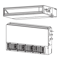
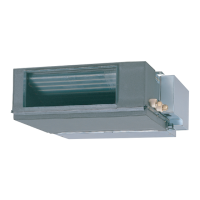
Shows installation dimensions and service access requirements for ceiling concealed units.

6.1B. Installation dimensions (Wall mounted type/Floor standing concealed type)

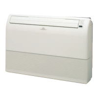
Displays installation dimensions for wall-mounted/floor-standing units, noting temperature correction setting.

6.2A. Install the unit (Ceiling concealed type)

Provides an example installation for ceiling concealed units, including duct connection.

INSTALL THE UNIT (Ceiling concealed type)

6.2A.2. INSTALL THE FILTERS

Instructions for installing filters into the unit.

6.2A.3. DRILLING HOLES FOR BOLTS AND INSTALLING THE BOLTS

Steps for drilling holes and installing mounting bolts using an installation template.

6.2A.4. FIX THE UNIT

Guidance on hanging the unit using hanger bolts and leveling it correctly.

Install the unit (Wall mounted type/ Floor standing concealed type)

6.2B.1. UNIT INSTALLATION EXAMPLE (Wall mounted type/Floor standing concealed type)

Example of duct connection for wall-mounted/floor-standing units.

Install the unit (Wall mounted type/ Floor standing concealed type)

6.2B.2. INSTALL THE FILTERS

Instructions for installing filters into the unit for wall-mounted/floor-standing types.

6.2B.3. INSTALL THE UNIT

Steps for securing the unit to the floor or wall and leveling it.

PIPE INSTALLATION

7.1. Selecting the pipe material

Guidelines for choosing appropriate copper pipes and materials for R410A systems.

7.2. Pipe requirement

Specifies requirements for pipe length, elevation difference, and heat insulation.

7.3. Flare connection (Pipe connection)

Details the process of connecting pipes using the flare method.

Installing heat insulation

7.3.1. Flaring

Step-by-step guide for flaring pipes using specific tools for R410A.

7.3.2. Bending pipes

Precautions and techniques for bending refrigerant pipes without causing damage.

7.3.3. Pipe connection

Instructions for correctly connecting pipes, including tightening flare nuts with a torque wrench.

7.4.1. COUPLER HEAT INSULATION

Guidance on applying coupler heat insulation to pipes and securing it.

INSTALLING DRAIN PIPES

8.1A. When drain pump is used

Instructions for installing drain pipes when a drain pump is utilized.

8.1B. When drain pump is not used (Natural drainage)

Instructions for installing drain pipes for natural drainage without a pump.

Wall mounted type / Floor standing concealed type

Details drain pipe installation for wall-mounted/floor-standing units.

Install the drain pipe

(1) Be sure to use supplied Drain hose ① and Hose band ②

Using supplied drain hose and hose band for installation.

(3) After installing the Drain hose, check if the drainage is smooth.

Verifying smooth drainage after installing the drain hose.

FINISH

Final steps for drain hose insulation, ensuring no gaps.

ELECTRICAL WIRING

Wiring Instructions

General guidelines for electrical wiring, including safety precautions and terminal connections.

INDOOR UNIT SIDE

(1)Remove the control box cover from the control box.

Steps to remove the control box cover for wiring access.

(2)Cable connection

Connecting power and remote controller cables to the terminal board.

(3) Wiring system diagram

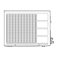
Shows the wiring diagram for indoor unit, disconnect switch, and outdoor unit/branch box.

REMOTE CONTROLLER SETTING

Setting Remote Controller Location

Guidelines for optimal placement of the remote controller for accurate temperature sensing.

10.1. Installing the remote controller

Detailed steps for mounting the remote controller and connecting its cable.

Setting the dip switches

Remote controller DIP switch settings

Explains the function of DIP switches on the remote controller.

Function setting

Function Setting Procedure

Step-by-step guide to enter and perform function settings using the remote controller.

10.3.1. Function Details

Details specific functions like Filter sign, Static pressure, Auto restart, etc.

10.3.2. Temperature Correction

How to adjust temperature settings based on building insulation and sensor location.

Jumper wire setting

(1) Drainage function setting (JM1)

Setting jumper wires for drainage function control.

(2) Fan delay setting (JM3)

Setting jumper wires for fan delay control.

Test run

CHECK ITEMS

List of critical checks to perform before and during the test run.

[OPERATION METHOD]

Procedure for initiating and stopping the test run operation.

SPECIAL INSTALLATION METHODS

DUAL REMOTE CONTROLLERS

Instructions for using two remote controllers to operate indoor units.

OPTIONAL PARTS

12.1. External input and external output

Details connection methods and wiring for external input/output options.

12.2. Remote sensor (Optional parts)

Instructions for connecting and setting up an optional remote sensor.

12.3. IR Receiver Unit (Optional parts)

Instructions for connecting an optional IR receiver unit.

ERROR CODES

Error Display and Codes

Table detailing error codes displayed on wired remote controllers and lamp blinking patterns.

CUSTOMER GUIDANCE

Customer Guidance Points

Key information to explain to the customer regarding operation and maintenance.

Related product manuals