2
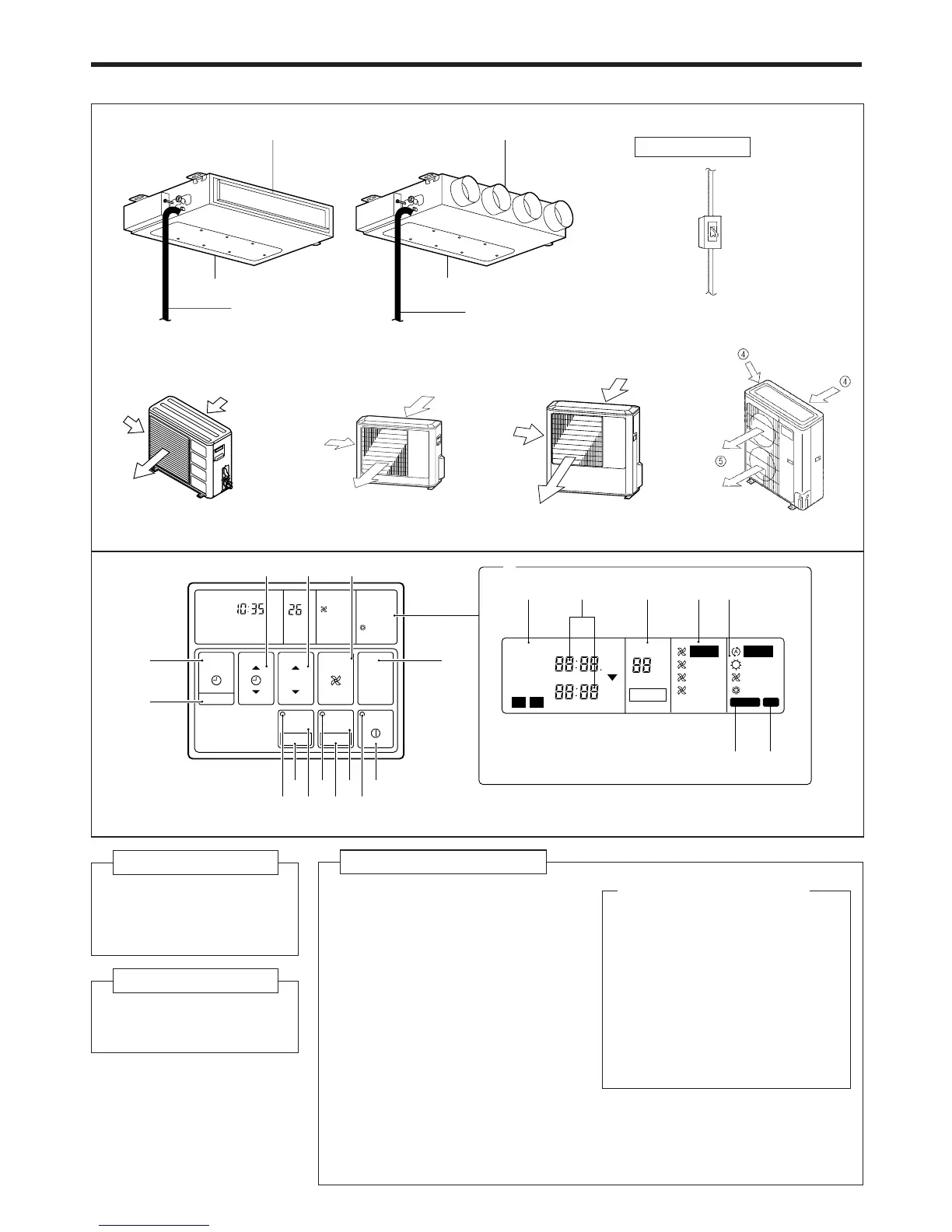
NAME OF PARTS
Fig. 4
● For explanatory purposes, the figure showing the remote
controller display shows all possible displays. The actual
display shows only that area that is being adjusted or used.
Fig. 5 Display
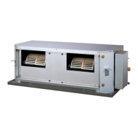
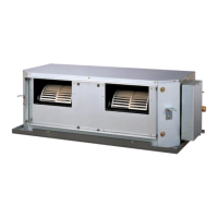
Fig. 1 Indoor Unit
1 Outlet Port
2 Intake Port
3 Drain Pipe
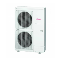
Fig. 2 Outdoor Unit
4 Air intake Port
5 Air outlet Port
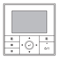
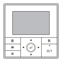
Fig. 4 Remote Controller
6 START/STOP Button
7 Operation Lamp
8 ENERGY SAVE Button
9 DAY OFF Button
0 ENERGY SAVE Lamp
A ZONE Control Button
B SET Button
C ZONE Control Lamp
D CLOCK ADJUST Button
E TIMER MODE Button
F SET TIME Button
G TEMP./DAY Button
H FAN CONTROL Button
I MASTER CONTROL Button
J Remote Controller Display
(Fig. 5)
K Ti mer Mode Display
L Clock Display (CLOCK/TIMER)
M Temperature/DAY Display
(TEMP./DAY)
N Fan Speed Display
O Operation Mode Display
P DEFROST Display
Q TEST Display
Instructions relating to heating (*) are applicable only to “HEAT & COOL MODEL” (Reverse Cycle).
°C
NON STOP
CLOCK
TEMP
AUTO
TIMER
MODE
SET
ZONE
START/STOP
CLOCK ADJUST
SET TIME TEMP./DAY FAN
CONTROL
MASTER
CONTROL
21
HIGH
COOL
DEFROST TEST
DAY OFF
ENERGY SAVE
°C
NON STOP
CLOCK
TIMER
NEXT DAY
DAY
TEMP.
OFFON
TIMER
WEEKLY
AUTO
OFF
ON
OFF
ON
DAY OFF
21
HIGH
MED
LOW
AUTO
HEAT
FAN
COOL
DEFROST TEST
*
C
0
A 79
B 8 6
F
E
I
D
G H
P
Q
K
J
LMNO
Fig. 1
Fig. 2
1
3
2
Fig. 3
This breaker is installed during
the electrical installation.
Electrical Breaker
1
2
3
•
Square Flange
•
Round Flange
4
4
5
4
5
4
4
4
5