En-10
13.2.4. Installing optional kits
Remote controller cable modication
(1)Useatooltocutofftheterminalontheendoftheremotecontrollercable,andthen
remove the insulation from the cut end of the cable.
(2)Connecttheremotecontrollercableandconnectingcable.
(Suppliedwithwiredremotecontroller.)
Important:Besuretoinsulatetheconnectionbetweenthecables.
20 mm
Remote
controller cable
Remote
controller cable
Red
Red
White
White
Black
Black
Insulated
connection
Connector
30 mm
35~45mm
150~160mm
Installing the wired remote controller terminal (sold separately)
Connectthewiredremotecontrollerterminaltotheconnector(CNC01)ontherelaycon-
trol board.
Relay wire
Connector:CNC01
Wiredremotecontrollercable
Rib
Installing the external connect kit terminal (sold separately)
Connectthewireofexternalinput/outputtotheboardofexternalconnectkit.
(
EXTERNALINPUTCONNECTTONO.CNA01
EXTERNALOUTPUTCONNECTTONO.CNB01,CNB02
)
External
connect kit cable
Error Status Output
connector:CNB02(Blackconnector)
Operation Status Output
connector:CNB01(Whiteconnector)
Control Input
(Operation/StoporForcedstop)
connector:CNA01(Whiteconnector)
Rib
Fixing the wires
Afterconnectingtheterminals,threadthewiresthroughtheclaspandribofthecontrolboxas
circledinthegurebelow.
Thenxthewiresontothecontrolboxwiththeprovidedcabletie.
Relay control board
Cable tie
13.2.5.
Installing the control cover
(1)
Attachthecontrolcover.
(2)
Attachthe2screws.
13.2.6.
Labelling
Pastethewiringlabelbesidethelabelforschematicdiagraminsidethefrontpanel.
13.2.7. Installing the front panel and intake grille
(See“9.FRONTPANELREMOVALANDINSTALLATION”and“9.2.Frontpanelinstallation”)
14.
SELECTING THE REMOTE CONTROLLER SIGNAL CODE
Whentwoormoreairconditionersareinstalledinaroomandtheremotecontrollerisop-
erating an air conditioner other than the one you wish to set, change the signal code of the
remotecontrollertooperateonlytheairconditioneryouwishtoset(4selectionspossible).
Whentwoormoreairconditionersareinstalledinaroom,pleasecontactyourretailerto
set the individual air conditioner signal codes.
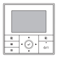
Selecting the Remote Controller Signal Code
Usethefollowingstepstoselectthesignalcodeoftheremotecontroller.(Notethatthe
air conditioner cannot receive a signal code if the air conditioner has not been set for the
signalcode.)
(1)PresstheSTART/STOP(
)buttonuntilonlytheclock
is displayed on the remote controller display.
(2)PresstheMODEbuttonforatleast5secondstodisplay
the current signal code (initially set to
).
(3)PresstheSETTEMP.(
/ )buttonstochangethe
signal code between
.
Match the code on the display to the air conditioner
signal code.
(4)PresstheMODEbuttonagaintoreturntotheclock
display. The signal code will be changed.
•Ifnobuttonsarepressedwithin30secondsafterthesignalcodeisdisplayed,the
system returns to the original clock display. In this case, start again from step 1.
•TheairconditionersignalcodeissettoApriortoshipment.
15. FUNCTION SETTING
Performthe“FUNCTIONSETTING”accordingtotheinstallationconditionsusingtheremote
controller.
CAUTION
•Conrmwhetherthewiringworkforoutdoorunithasbeennished.
•Conrmthatthecoverfortheelectricalenclosureontheoutdoorunitisinplace.
• Thisprocedurechangestothefunctionsettingsusedtocontroltheindoorunitaccording
to the installation conditions. Incorrect settings can cause the indoor unit to malfunction.
• Afterthepoweristurnedon,performthe“FUNCTIONSETTING”accordingtothe
installation conditions using the remote controller.
• Thesettingsmaybeselectedbetweenthefollowingtwo:FunctionNumberorSetting
Value.
• Settingswillnotbechangedifinvalidnumbersorsettingvaluesareselected.
• Refertotheinstallationmanualenclosedwiththeremotecontrolunitwhenthewired
remotecontrolunit(option)isused.
Entering the Function Setting Mode
WhilepressingthePOWERFULbuttonandSETTEMP.( )simultaneously,pressthe
RESET button to enter the function setting mode.
Selecting the Function Number and Setting Value
[Reverse cycle model]
(1) Press the TEMP. (
/ ) buttons to select the func-
tion number. (Press the 10°C HEAT button to switch
betweentheleftandrightdigits.)
(2) Press the POWERFULbutton to proceed to setting
value.(PressthePOWERFULbuttonagaintoreturnto
thefunctionnumberselection.)
(3) PresstheTEMP.(
/ )buttonstoselectthesetting
value.(Pressthe10°C HEATbuttontoswitchbetween
theleftandrightdigits.)
(4) Press the MODE button, and START/STOP button, in
theorderlistedtoconrmthesettings.
(5) PresstheRESETbuttontocancelthefunctionsetting
mode.
(6) Aftercompleting theFUNCTION SETTING,be sureto
turn off the power and turn it on again.
Function Number
Setting
Value
 Loading...