. THERMO CONTROL ( FOR INDOOR UNIT SENSOR )
19
. THERMO CONTROL ( FOR WIRED REMOTE SENSOR )
20
. HEAT INSULATION CONDITION ( BUILDING INSULATION )
18
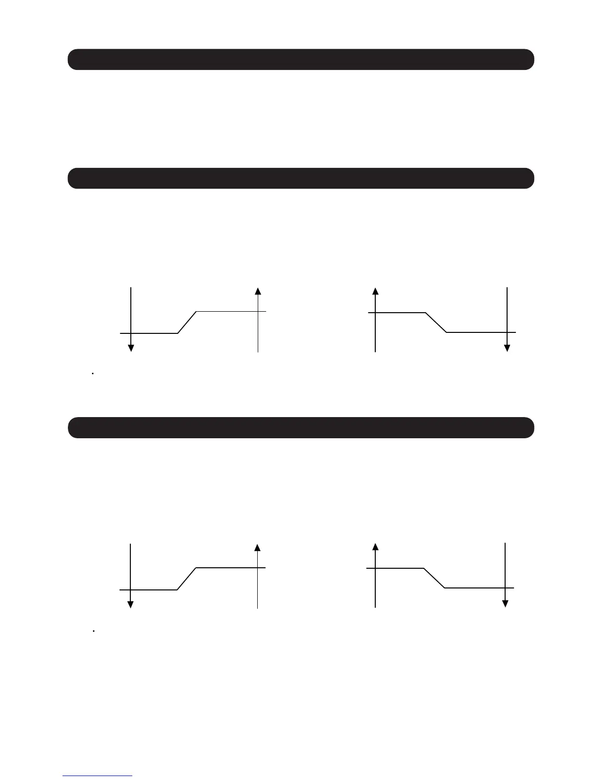
Ts + 1°F
(Ts + 0.5°C)
Ts - 1°F
(Ts - 0.5°C)
Ts - 1°F
(Ts - 0.5°C)
Ts + 1°F
Compressor ON
(Ts + 0.5°C)
( Fig. 14 : For Cooling operation )
Ts+ 1°F
(Ts + 0.5°C)
Ts- 1°F
(Ts - 0.5°C)
Ts
Ts
Compressor OFF
( Fig. 15 : For Heating operation )
Compressor ON
Compressor OFF
Ts : Setting temperature
Ts : Setting temperature
Compressor ON
Compressor OFF
Compressor ON
Compressor OFF
( Fig. 16 : For Cooling operation ) ( Fig. 17 : For Heating operation )
This setting can make the room temperature control more suitable for homes or buildings
with high insulation (Function Number 95).
When the thermo sensor is turned ON it controls the compressor frequency at
initial start to prevent overshoot in heating or cooling.
When room temperature is controlled by the Indoor unit sensor, compressor operation
is as shown in Fig. 14 and 15.
But, adjustment is possible by the room temperature correction function setting.
(Function Number 30 or 31)
When room temperature is controlled by the Wired remote sensor, compressor
operation is as shown in Fig. 16 and 17.
But, adjustment is possible by the room temperature correction function setting.
(Function Number 92 or 93)
01-22
 Loading...