Do you have a question about the Fujitsu ARXG22KMLB and is the answer not in the manual?
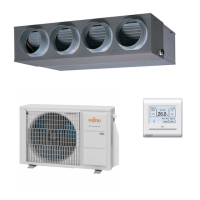
Presents a visual lineup of available indoor and outdoor unit models.
Details how to connect indoor units for 4-unit multi-split systems.
Provides detailed specifications for compact cassette indoor units.
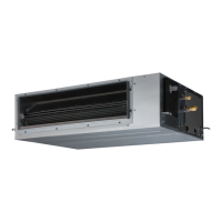
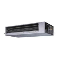
Provides detailed specifications for mini duct indoor units.
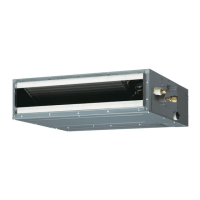
Provides detailed specifications for slim duct indoor units.
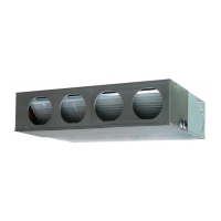
Provides detailed specifications for medium static pressure duct indoor units.
Provides detailed specifications for wall mounted indoor units.
Provides detailed specifications for ceiling type indoor units.
Provides detailed specifications for floor type indoor units.
Shows dimensional drawings and installation space requirements for compact cassette units.
Shows dimensional drawings and installation space requirements for mini duct units.
Shows dimensional drawings and installation space requirements for slim duct units.
Shows dimensional drawings and installation space requirements for medium static pressure duct units.
Shows dimensional drawings and installation space requirements for wall mounted units.
Shows dimensional drawings and installation space requirements for ceiling type units.
Shows dimensional drawings and installation space requirements for floor type units.
Provides wiring diagrams for compact cassette indoor units.
Provides wiring diagrams for mini duct and slim duct indoor units.
Provides wiring diagrams for medium static pressure duct units.
Provides wiring diagrams for wall mounted indoor units.
Provides wiring diagrams for ceiling type indoor units.
Provides wiring diagrams for floor type indoor units.
Shows air velocity and temperature distribution for compact cassette units.
Shows air velocity and temperature distribution for mini duct units.
Shows air velocity and temperature distribution for slim duct units.
Shows air velocity distribution for wall mounted units.
Shows air velocity distribution for ceiling type units.
Shows air velocity distribution for floor type units.
Provides fan performance curves and capacity data for mini duct units.
Provides fan performance curves and capacity data for slim duct units.
Provides fan performance curves and capacity data for medium static pressure duct units.
Lists airflow rates (m³/h, l/s, CFM) for compact cassette indoor units.
Lists airflow rates (m³/h, l/s, CFM) for mini duct indoor units.
Lists airflow rates (m³/h, l/s, CFM) for slim duct indoor units.
Lists airflow rates (m³/h, l/s, CFM) for medium static pressure duct units.
Lists airflow rates (m³/h, l/s, CFM) for wall mounted indoor units.
Lists airflow rates (m³/h, l/s, CFM) for ceiling type indoor units.
Lists airflow rates (m³/h, l/s, CFM) for floor type indoor units.
Shows noise level curves (dB) for compact cassette units at various frequencies.
Shows noise level curves (dB) for mini duct units at various frequencies.
Shows noise level curves (dB) for slim duct units at various frequencies.
Shows noise level curves (dB) for medium static pressure duct units.
Shows noise level curves (dB) for wall mounted units.
Shows noise level curves (dB) for ceiling type units.
Shows noise level curves (dB) for floor type units.
Illustrates microphone placement for measuring sound levels for various unit types.
Explains external input/output connections and functions for specific indoor unit types.
Details external input/output PCB and connections for specific wall-mounted models.
Explains external input/output functions and circuit diagrams for specific wall-mounted models.
Details external input/output PCB, external input, and external output for ceiling type units.
Explains combination of external input/output and input signal types for floor units.
Provides an overview of the AR-REW4E, AR-REM4E, and AR-REB1E wireless remote controllers.
Provides an overview of the AR-REW2E wireless remote controller.
Provides an overview of the AR-REM7E wireless remote controller.
Overview of the UTY-LNTY wireless remote controller.
Overview of the IR receiver kit with Wireless remote controller.
Overview of the UTY-RNNYM wired remote controller, including button functions.
Overview of the UTY-RLRY wired remote controller, including button functions.
Overview of the UTY-RVNYM wired remote controller.
Overview of the UTY-RNRYZ* wired remote controller.
Overview of the UTY-RSNYM simple remote controller.
Overview of the UTY-RSRY and UTY-RHRY simple remote controllers.
Explains function settings adjustment via DIP switches on the PCB.
Details the preparation and procedure for setting functions using a wireless remote controller.
Explains the procedure for setting functions using a wired remote controller.
Details the procedure for setting functions using a simple remote controller.
Lists all adjustable function settings and their availability for different unit types.
Lists accessories included for compact cassette type indoor units.
Lists accessories included for mini duct type indoor units.
Lists accessories included for slim duct type indoor units.
Lists accessories included for medium static pressure duct type units.
Lists accessories included for wall mounted indoor units.
Lists accessories included for ceiling type indoor units.
Lists accessories included for floor type indoor units.
Summarizes the lineup of available wireless and wired remote controllers.
Lists optional cassette grilles.
Lists other optional parts like converters, adapters, and filters.
Lists locations where indoor units should not be installed due to safety hazards.
Provides important installation considerations and countermeasures for specific conditions.
Provides detailed electrical and mechanical specifications for the AOYG30KBTA4 outdoor unit.
Shows dimensional drawings of the AOYG30KBTA4 outdoor unit.
Details required installation space around the outdoor unit for proper operation and maintenance.
Illustrates the refrigerant circuit diagram for the AOYG30KBTA4 outdoor unit.
Provides the electrical wiring diagram for the AOYG30KBTA4 outdoor unit.
Lists combinations of indoor units and their total capacity ratings for cooling.
Provides cooling capacity data (TC, IP) for various indoor/outdoor temperature conditions for AOYG30KBTA4.
Provides heating capacity data (TC) for various indoor/outdoor temperature conditions for AOYG30KBTA4.
Details refrigerant amount and additional charge calculation based on pipe length for AOYG30KBTA4.
Lists airflow rates (m³/h, l/s, CFM) for cooling and heating operations for AOYG30KBTA4.
Shows noise level curves (dB) for cooling and heating operations at various frequencies for AOYG30KBTA4.
Illustrates microphone placement for measuring sound levels for outdoor units.
Summarizes electrical specifications including voltage, current, and wiring requirements.
Details safety devices like fuses, thermal protectors, and compressor protection mechanisms.
Explains how to adjust outdoor unit settings using DIP switches and push buttons on the PCB.
Details how to enable and use the optional outdoor unit low noise operation function.
Explains how to change the outdoor unit current limit function.
Explains the check run function for detecting wiring errors and automatic wiring correction.
Details the procedure for performing a test run to check system operation and confirm wiring.
Lists error codes and their descriptions to help diagnose problems for outdoor units.
Provides instructions for performing pump down operation for refrigerant recovery.
Lists accessories included with the AOYG30KBTA4 outdoor unit.
Lists optional parts like remote controllers and communication kits.
Lists locations where outdoor units should not be installed due to safety hazards.
Provides important installation considerations for outdoor units.
Provides detailed electrical and mechanical specifications for the AOYG36KBTA5 outdoor unit.
Shows dimensional drawings of the AOYG36KBTA5 outdoor unit.
Details required installation space around the outdoor unit for proper operation and maintenance.
Illustrates the refrigerant circuit diagram for the AOYG36KBTA5 outdoor unit.
Provides the electrical wiring diagram for the AOYG36KBTA5 outdoor unit.
Lists combinations of indoor units and their total capacity ratings for cooling.
Provides cooling capacity data (TC, IP) for various indoor/outdoor temperature conditions for AOYG36KBTA5.
Provides heating capacity data (TC) for various indoor/outdoor temperature conditions for AOYG36KBTA5.
Provides compensation rates for pipe length and height differences for AOYG36KBTA5 units.
Details refrigerant amount and additional charge calculation based on pipe length for AOYG36KBTA5.
Lists airflow rates (m³/h, l/s, CFM) for cooling and heating operations for AOYG36KBTA5.
Shows noise level curves (dB) for cooling and heating operations at various frequencies for AOYG36KBTA5.
Illustrates microphone placement for measuring sound levels for outdoor units.
Summarizes electrical specifications for the AOYG36KBTA5 outdoor unit.
Details safety devices for the AOYG36KBTA5 outdoor unit.
Explains how to adjust outdoor unit settings using DIP switches and push buttons on the PCB.
Details how to change the outdoor unit current limit function.
Explains the check run function for detecting wiring errors and automatic wiring correction.
Details the procedure for performing a test run to check system operation and confirm wiring.
Lists error codes and their descriptions to help diagnose problems for outdoor units.
Provides instructions for performing pump down operation for refrigerant recovery.
Lists accessories included with the AOYG36KBTA5 outdoor unit.
Lists optional parts like remote controllers and communication kits.
Lists locations where outdoor units should not be installed due to safety hazards.
Provides important installation considerations for outdoor units.
| Brand | Fujitsu |
|---|---|
| Model | ARXG22KMLB |
| Category | Air Conditioner |
| Language | English |