Do you have a question about the Fujitsu ARXG24KMLA and is the answer not in the manual?
Technical specifications for compact cassette indoor units covering airflow, power, and dimensions.
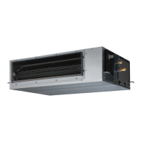
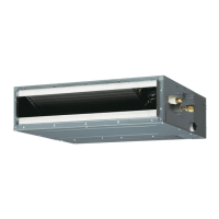
Technical specifications for slim duct indoor units, detailing performance and dimensions.
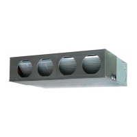
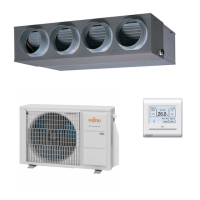
Technical specifications for duct type indoor units, including airflow and electrical data.
Dimensional drawings and specifications for compact cassette indoor units.
Dimensional drawings and specifications for slim duct indoor units.
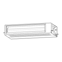
Dimensional drawings and specifications for duct type indoor units.
Specifies the required installation space for duct type indoor units.
Specifies the required maintenance space for duct type indoor units.
Illustrates electrical wiring diagrams for different indoor unit types.
Wiring diagrams specific to compact cassette indoor units.
Wiring diagrams specific to slim duct indoor units.
Wiring diagrams specific to duct type indoor units.
Details electrical specifications, including power supply and wiring.
Information on safety devices like fuses and thermal protectors.
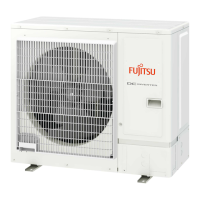
Provides key technical specifications for outdoor units.
Presents dimensional data for outdoor units.
Dimensional drawings for the AOYG36KRTA outdoor unit.
Specifies required installation space for outdoor units.
Installation space requirements for specified outdoor unit models.
Installation space guidelines for multiple outdoor units.
Guidelines for installing outdoor units in multi-row configurations.
General precautions for system installation.
Specific precautions for indoor unit installation.
Specific precautions for outdoor unit installation.
Covers important aspects of refrigerant pipe design and selection.
Key considerations for using R32 refrigerant in piping.
Limits and rules for refrigerant piping length and height differences.
Piping limitations for twin indoor unit systems.
Piping limitations for triple indoor unit systems.
Guidelines for selecting appropriate pipe sizes.
Guide to selecting appropriate pipe sizes for the system.
Provides guidelines and cautions for refrigerant pipe installation.
Important cautions and guidelines for piping installation.
Procedure for piping connections to the outdoor unit.
Steps and cautions for connecting refrigerant pipes.
Precautions for connecting multi-operation systems.
Steps and cautions for connecting refrigerant pipes.
Details electrical wiring design considerations.
Essential precautions for safe and correct electrical wiring.
Specifications and guidelines for power supply cables.
Details wiring configurations for power supply cables.
Rules and best practices for wiring connections.
Explains the overall wiring method and diagrams.
Recommended wiring connection examples for multi-unit systems.
Details various function settings and configurations.
Settings and controls for the outdoor unit PCB and switches.
Explains the functions of outdoor unit switch buttons and LEDs.
Table detailing function settings and corresponding LED displays.
Procedure for setting functions locally on the outdoor unit.
Step-by-step guide for setting the low noise mode.
Step-by-step guide for setting the peak cut mode.
Function settings for compact cassette units using DIP switches.
Function settings for slim duct units using DIP switches.
Function settings for duct units using DIP switches.
Location of DIP switches on the indoor unit PCB.
Details DIP switch settings for various functions.
Setting remote controller addresses using SW100.
Setting functions using a wireless remote controller.
Button functions and overview of UTY-LNTY remote controller.
Setting functions using a wired remote controller.
Button functions and overview of UTY-RNNYM remote controller.
Setting functions using a simple remote controller.
Preparation steps before setting simple remote controller functions.
Button functions and overview of UTY-RSNYM remote controller.
Explains the buttons and functions of the UTY-RSNYM controller.
Step-by-step procedure for setting functions via simple remote.
Procedure for setting up individual indoor units with simple remote.
Power reset procedure after setting up all units.
Detailed explanation of various function settings.
Lists adjustable function settings.
Table summarizing function settings for different unit types.
Setting for refrigerant circuit address.
Setting custom codes for wireless remote controllers.
Procedures for checking and testing the system.
Steps for performing a test run of the system.
Items to check before performing a test run.
Method for conducting test operations.
Checklist of items to verify during test operation.
Lists and explains error codes for troubleshooting.
How errors are displayed on the unit.
Table detailing error codes and their meanings.
Procedure for pump down operation.
Step-by-step guide for pump down.
| Heating Capacity | 8.0 kW |
|---|---|
| Energy Efficiency Ratio (EER) | 3.21 |
| Energy Efficiency Class Cooling | A++ |
| Energy Efficiency Class Heating | A+ |
| Power Supply | 220-240V, 50Hz |
| Refrigerant | R32 |