En-5
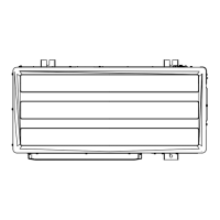
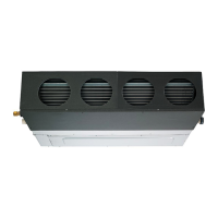
Replace the cover as follows.
• Remove the screws, and then remove cover and fan guard.
• Install the cover with the screws as shown in the illustration below.
Model Screw
7000, 9000, 12000, 14000 Btu/h 9
18000 Btu/h 11
Screw
Cover
Fan guard
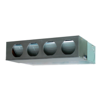
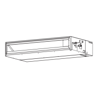
Side Inlet - Side Outlet
Insulation material (Field supply)
Aluminum tape
Flange (Field supply)
Air
Duct
(Field supply)
Air
Intake grille
(Field supply)
Side Inlet - Side Outlet (Duct)
Insulation material (Field supply)
Aluminum tape
Aluminum tape
Tapping screw for
fl ange connection
(M4 x 10mm /
Field supply)
Flange (Field supply)
Flange (Field supply)
Air
Duct
(Field supply)
Air
Intake grille
(Field supply)
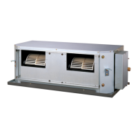
Bottom Inlet - Side Outlet
Duct (Field supply)
Intake grille (Field supply)
Air
Air
Outlet side
Inlet side
7000, 9000, 12000, 14000 Btu/h 18000 Btu/h
A 650 mm 850 mm
B P200×2=400 mm P200×3=600 mm
CAUTION
Be sure to install the air inlet grille and the air outlet grille for air circulation. The correct
temperature cannot be detected.
Grills must be fixed so that man cannot touch indoor unit fan and exchanger, and
cannot be removed by only hand operation without tool.
Be sure to install the air fi lter in the air inlet.
If the air fi lter is not installed, the heat exchanger may be clogged and its performance
may decrease.
3.3A.2. INSTALL THE FILTERS
• Install the fi lters to the unit.
Filter (Accessories)
Unit
Filter
3.3A.3.
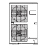
DRILLING HOLES FOR BOLTS AND INSTALLING THE BOLTS
• Using the installation template, drill holes for bolts (4 holes).
Drilling position
for bolts
Installation template
A
Air
377 mm
7000, 9000, 12000, 14000 Btu/h 18000 Btu/h
A 734 mm 934 mm
9374342235-02_IM.indb 5 4/2/2012 2:35:39 PM
www.ampair.co.uk | sales@ampair.co.uk
 Loading...