En-6
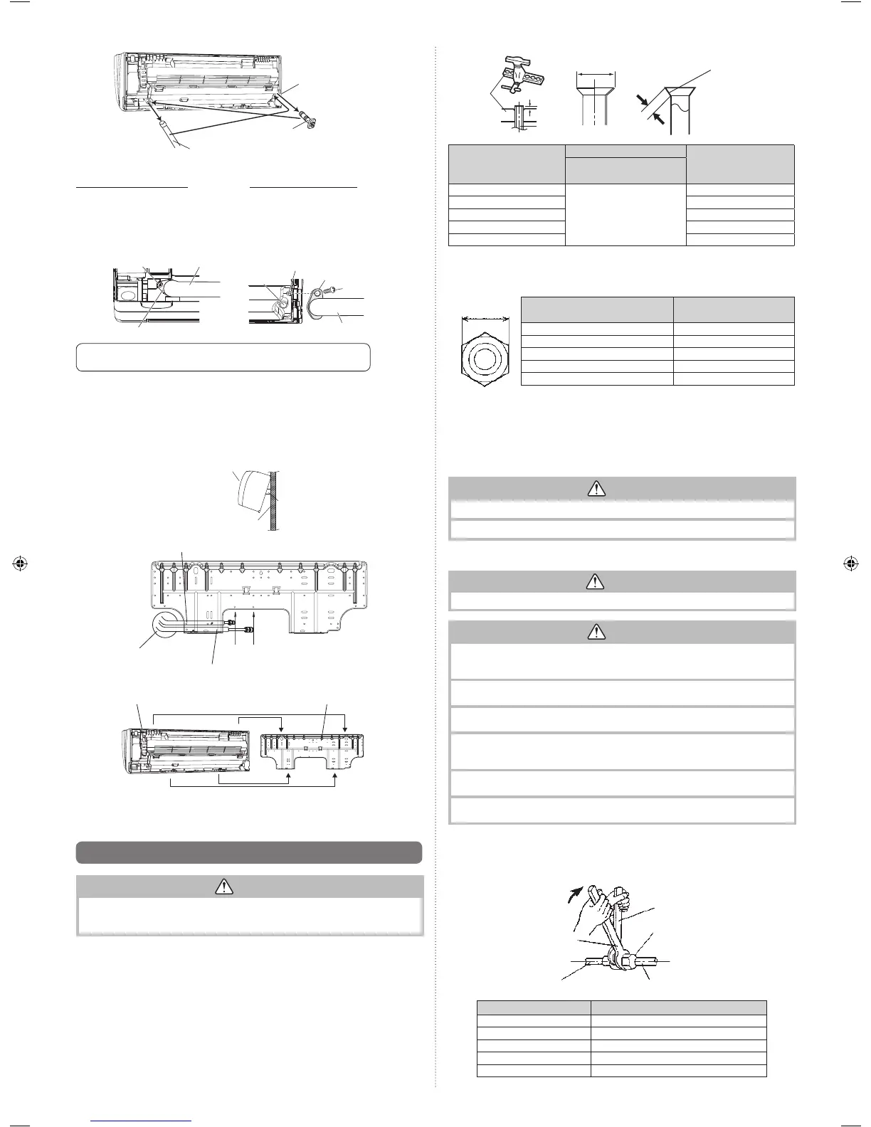
For left outlet piping (Drain
hose), cut off the piping
outlet cutting groove with a
hacksaw.
Indoor unit
drain hose
Drain cap
Remove the drain cap by pull-
ing at the projection at the end
of the cap with pliers, etc.
Removing the drain hose
Remove the screw at the left of
drain hose and pull out drain hose.
Installing the drain hose
Vertically insert the drain hose toward the
inside, so that the drain fi xture (white) can ac-
curately align with the screw hole around the
drain cock.
After inserting and before replacing, please
reinstall and fi x the removed screws.
• Please hold around the joint of the drain hose during work.
•
As the screw is inside, be sure to use screwdrivers treated with magnet.
Screw
Drain fixture
Drain hose
Screw hole
Drain cock
Drain hose
Screw
Drain fixture
• After passing the indoor piping and drain hose through the wall hole, hang the indoor unit
on the hooks at the top and bottom of the wall hook bracket.
[Installing the indoor unit]
• Hang the indoor unit from the hooks at the top of the wall hook bracket.
• Insert the spacer, etc. between the indoor unit and the wall hook bracket and separate
the bottom of the indoor unit from the wall.
Indoor unit
Wall hook bracket
(Spacer)
Connection pipe small
Align the marks
Connection pipe large
Bend 70 with a
pipe bender
Indoor unit
Top hooks
Bottom hooks
Wall hook bracket
• After hooking the indoor unit to the top hook, hook the fi ttings of the indoor unit to the 2
bottom hooks while lowering the unit and pushing it against the wall.
6.6. Flare connection (Pipe connection)
CAUTION
Tighten the flare nuts with a torque wrench using the specified tightening method.
Otherwise, the fl are nuts could break after a prolonged period, causing refrigerant to leak
and generate hazardous gas if the refrigerant comes into contact with a fl ame.
6.6.1. Flaring
Use special pipe cutter and fl are tool designed for R410A or R32 pipework.
(1) Cut the connection pipe to the necessary length with a pipe cutter.
(2) Hold the pipe downward so that cuttings will not enter the pipe and remove any burrs.
(3)
Insert the fl are nut (always use the fl are nut attached to the indoor unit(s) and outdoor unit
or branch box respectively) onto the pipe and perform the fl are processing with a fl are
tool. Use the special R410A or R32 fl are tool, or the conventional fl are tool. Leakage of
refrigerant may result if other fl are nuts are used.
(4) Protect the pipes by pinching them or with tape to prevent dust, dirt, or water from
entering the pipes.
Die
A
Pipe
B
L
Check if [L] is flared uniformly
and is not cracked or scratched.
Pipe outside diameter
[mm (in.)]
Dimension A [mm]
Dimension B [mm]
Flare tool for R32,
clutch type
6.35 (1/4)
0 to 0.5
9.1
9.52 (3/8) 13.2
12.70 (1/2) 16.6
15.88 (5/8) 19.7
19.05 (3/4) 24.0
When using conventional fl are tools to fl are R32 pipes, the dimension A should be approx-
imately 0.5 mm more than indicated in the table (for fl aring with R32 fl are tools) to achieve
the specifi ed fl aring. Use a thickness gauge to measure the dimension A.
Width across
flats
Pipe outside diameter [mm (in.)]
Width across flats
of Flare nut [mm]
6.35 (1/4) 17
9.52 (3/8) 22
12.70 (1/2) 26
15.88 (5/8) 29
19.05 (3/4) 36
6.6.2. Bending pipes
• If pipes are shaped by hand, be careful not to collapse them.
• Bend R70 mm or more with a pipe bender.
• Do not bend the pipes in an angle more than 90°.
• When pipes are repeatedly bend or stretched, the material will harden, making it diffi cult
to bend or stretch them any more.
• Do not bend or stretch the pipes more than 3 times.
CAUTION
To prevent breaking of the pipe, avoid sharp bends.
If the pipe is bent repeatedly at the same place, it will break.
6.6.3. Pipe connection
WARNING
The fl are connection shall not be performed indoors.
CAUTION
Be sure to Install the pipe against the port on the indoor unit correctly. If the centering
is improper, the fl are nut cannot tighten smoothly. If the fl are nut is forced to turn, the
threads will be damaged.
Do not remove the fl are nut from the indoor unit pipe until immediately before con-
necting the connection pipe.
Hold the torque wrench at its grip, keeping it in the right angle with the pipe, in order
to tighten the fl are nut correctly.
Tighten the fl are nuts with a torque wrench using the specifi ed tightening method.
Otherwise, the fl are nuts could break after a prolonged period, causing refrigerant to
leak and generate hazardous gas if the refrigerant comes into contact with a fl ame.
Connect the piping so that the control box cover can easily be removed for servicing
when necessary.
In order to prevent water from leaking into the control box, make sure that the piping
is well insulated.
When the flare nut is tightened properly by your hand, hold the body side coupling with a
wrench, then tighten with a torque wrench. (See the table below for the flare nut tightening
torques.)
Tighten with 2 wrenches.
Holding wrench
Flare nut
Connection pipe
Torque wrench
Indoor unit pipe
(Body side)
Flare nut [mm (in.)] Tightening torque [N·m (kgf·cm)]
6.35 (1/4) dia. 16 to 18 (160 to 180)
9.52 (3/8) dia. 32 to 42 (320 to 420)
12.70 (1/2) dia. 49 to 61 (490 to 610)
15.88 (5/8) dia. 63 to 75 (630 to 750)
19.05 (3/4) dia. 90 to 110 (900 to 1,100)
9333005201_IM_En_ASTG09KMCA.indd 69333005201_IM_En_ASTG09KMCA.indd 6 2017/1/20 11:43:052017/1/20 11:43:05