Do you have a question about the Fujitsu ASTG34JFCC and is the answer not in the manual?
Details on voltage, current, power, efficiency, and capacity.
Sound pressure levels for indoor and outdoor units at different settings.
Information on compressor type, refrigerant, charge, and pipe specifications.
Physical sizes of the indoor and outdoor units.
Shipping and net weight for indoor and outdoor units.
Specifications for indoor and outdoor unit fan motors, including speed.
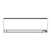
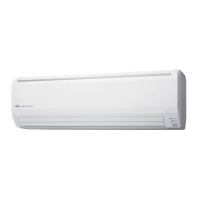
Detailed measurements and diagrams for the indoor unit.
Detailed measurements and diagrams for the outdoor unit.
Length and diameter of the drain hose.
Schematic illustrating refrigerant flow and key components.
Specifies the diameter for liquid and gas refrigerant pipes.
Electrical schematic for the indoor unit's control system.
Electrical schematic for the outdoor unit's control system.
Details PCB connections for main, indicator, and control units.
Wiring diagram for louvers, diffuser, and fan motors.
Circuit diagram for the indicator PCB, showing LEDs and ICs.
Schematic of the outdoor unit's main and filter PCBs.
Circuit diagram for the outdoor unit's filter PCB.
Details power distribution and connections on the main PCB.
Circuit diagram for the IPM transistor PCB.
Diagram of components on the outdoor unit filter PCB.
Schematic of LEDs and switches on the outdoor indicator PCB.
Circuit diagram for the demand control option PCB.
Table of indoor unit LED patterns and corresponding error codes.
List of error codes displayed on a wired remote control.
Explains LED patterns on the outdoor unit for error detection.
Detailed table of outdoor unit error codes and descriptions.
Items to check before performing the test run.
Procedures for setting up cooling and heating test modes.
Safety warnings and preparation steps for pump down.
Detailed steps for performing the pump down operation.
Explains the three DR modes and their impact on operation.
Exploded view and parts list for the indoor unit's external parts.
Exploded view and parts list for internal indoor unit components.
Exploded view and parts list for the indoor unit casing.
Exploded view and parts list for outdoor unit main parts.
Exploded view and parts list for outdoor unit control box parts.
Diagrams and parts list for outdoor unit refrigerant system components.
List of optional accessories for the indoor unit.
List of optional accessories for the outdoor unit.
Parts list for the demand control option PCB kit.
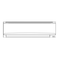
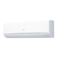
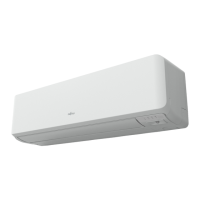
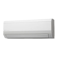
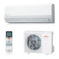
This document is a service manual for Fujitsu split-type room air conditioners, specifically models ASTG34JFCC and ASTG34LFCC (indoor units) and AOTG34JFTC and AOTG34LFTC (outdoor units), which utilize R410A refrigerant. It provides comprehensive information for installation, maintenance, and troubleshooting.
The Fujitsu split-type room air conditioner is designed for both cooling and heating, providing climate control for indoor spaces. It operates as a split system, with an indoor unit responsible for air delivery and an outdoor unit housing the compressor and main heat exchange components. The system incorporates DC inverter motor technology for efficient operation and precise temperature control. The manual details the electrical data, noise levels, compressor and refrigerant specifications, dimensions, and fan motor characteristics for both indoor and outdoor units. It also includes detailed circuit diagrams for the indoor and outdoor PCBs, as well as an indicator PCB, to aid in understanding the electrical and control logic. Error detection codes and troubleshooting procedures are provided to assist service personnel in diagnosing and resolving system malfunctions. Furthermore, the manual outlines a "Demand Response" feature, allowing the air conditioner to adjust its operation based on signals from an electricity supplier to manage energy consumption during peak demand periods. A pump-down procedure is also described for safely recovering refrigerant during servicing.
| Brand | Fujitsu |
|---|---|
| Model | ASTG34JFCC |
| Category | Air Conditioner |
| Language | English |