Do you have a question about the Fujitsu ASU24CL and is the answer not in the manual?
Details noise levels for indoor and outdoor units in dB.
Provides electrical specs, refrigerant charge, and related data.
Details compressor and fan motor specifications including power source and RPM.
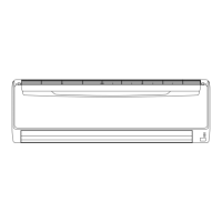
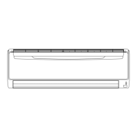
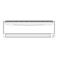
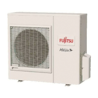
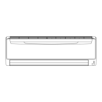
Provides physical dimensions and weight for indoor and outdoor units.
Circuit diagrams for indoor unit components including controller, fan, and motors.
Circuit diagrams for outdoor unit components including controller, power supply, and compressor.
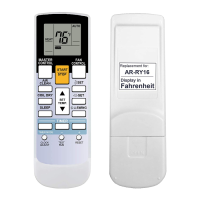
Diagram showing connections for the indoor control unit and remote controller.
Circuit diagram for indoor unit motors (fan, louver, diffuser) and actuators.
Circuit diagram for indoor unit sensors like room and pipe temperature thermistors.
Diagram for outdoor unit power supply, DC fan motor, and compressor connections.
Circuit diagram for outdoor unit control PCBs, valves, and thermistor connections.
Diagrams for outdoor unit inverter and TR PCB (IPM) systems.
Details serial signal error codes, LED flashes, and descriptions.
Covers indoor and outdoor unit thermistor errors, including open/short conditions.
Lists errors related to indoor/outdoor unit control, fan motor, and refrigerant cycle.
Details optional function errors and model errors with LED indications.
List of part numbers and descriptions for the indoor unit assembly.
List of part numbers and descriptions for the outdoor unit assembly.
| Brand | Fujitsu |
|---|---|
| Model | ASU24CL |
| Category | Air Conditioner |
| Language | English |