Do you have a question about the Fujitsu ASU24RLQ and is the answer not in the manual?
Details noise levels for indoor and outdoor units across various operating modes.
Covers power source, frequency, current, input watts, E.E.R., COP, and moisture removal.
Information on compressor type, refrigerant, fan motor power source, and RPM.
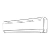
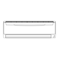
Provides physical dimensions (H x W x D) and weight (Gross/Net) for indoor and outdoor units.
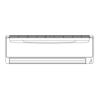
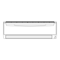
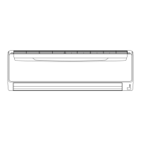
Visual representation of the indoor unit's dimensions with detailed measurements.
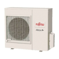
Visual representation of the outdoor unit's dimensions with detailed measurements.
Diagram illustrating the refrigerant path, valves, heat exchangers, and pipe diameters for cooling/heating.
Overall circuit diagram connecting indoor and outdoor units and major components.
Detailed circuit diagram for the indoor unit's controller and indicator PCBs.
Detailed circuit diagrams for the outdoor unit's various PCBs and assemblies.
Lists error codes, display indications (Operation LED, Timer LED), and their corresponding error descriptions.
Visual guide showing the exploded view and part numbers for indoor unit disassembly.
Visual guide showing the exploded view and part numbers for outdoor unit disassembly.
Comprehensive list of indoor unit parts with reference numbers, descriptions, and part numbers.
Comprehensive list of outdoor unit parts with reference numbers, descriptions, and part numbers.
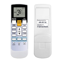
Lists standard accessories included with the air conditioner, along with their part numbers.
| Cooling Capacity | 24000 BTU/h |
|---|---|
| Heating Capacity | 24000 BTU/h |
| Refrigerant | R410A |
| Type | Split System |
| Seasonal Energy Efficiency Ratio (SEER) | 16.0 |
| Power Supply | 230 V, 50 Hz |