Do you have a question about the Fujitsu ASU24CL1 and is the answer not in the manual?
Details the DC fan motor, PAM control, and DC compressor technology for improved performance.
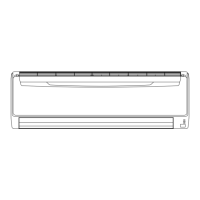
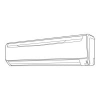
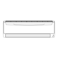
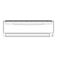
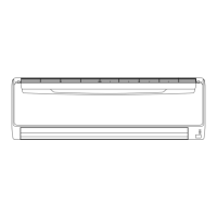
Describes how the power diffuser directs airflow to avoid direct occupant exposure for comfort.
Notes the unit's capability for cooling operation at low outdoor temperatures (-10°C).
Specifies the maximum allowable pipe length for installation, ensuring performance.
Details the different filters (Ion Deodorization, Apple-catechin, Pre-filter) for improved air quality.
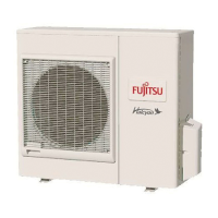
Explains the blue fin treatment for enhanced corrosion resistance, especially in coastal environments.
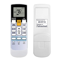
Covers the features, timers, and signal code selection of the wireless remote controller.
Details the various buttons and their operations on the remote controller for managing the AC.
Explains the indicators and symbols shown on the remote controller's display screen.
Provides comprehensive technical specifications for the indoor unit, including capacity, power, and dimensions.
Presents detailed dimensional drawings and measurements for the indoor unit and its installation clearances.
Provides critical clearance and space requirements for proper installation of the indoor unit.
Illustrates the electrical connections and internal wiring schematics for the indoor unit.
Presents detailed cooling capacity data across various indoor and outdoor temperature conditions.
Details fan performance metrics, including air velocity distribution and airflow rates.
Illustrates airflow patterns at different fan speeds and flap positions.
Lists the air flow rates (m³/h, l/s, CFM) for different fan speeds.
Provides information on the operational noise levels, including noise level curves and check points.
Shows sound pressure levels across different frequency bands for various fan speeds.
Illustrates the microphone placement for measuring sound levels.
Details the electrical properties of the indoor unit, such as voltage, frequency, and current.
Lists the safety features and protection mechanisms implemented in the indoor unit.
Explains functionalities for external control inputs and status outputs of the unit.
Explains how to use external switches for remote operation control (ON/STOP).
Describes how to output the unit's operation status signal for external monitoring.
Details various functional settings and configurations available for the indoor unit.
Details function settings for the indoor unit, including jumper wire configurations.
Explains jumper wire settings for Auto Restart, Room Temp Correction, and Signal Code.
Provides steps to select and match the remote controller signal code with the unit.
Lists and describes optional accessories available for the air conditioner system.
Provides comprehensive technical specifications for the outdoor unit, including capacity, power, and dimensions.
Presents detailed dimensional drawings and measurements for the outdoor unit and its installation clearances.
Specifies the required clearances and service space for the outdoor unit installation.
Illustrates the refrigerant flow path and components within the air conditioning system.
Illustrates the electrical connections and internal wiring schematics for the outdoor unit.
Provides adjustment factors for capacity based on pipe length and height differences.
Details the procedure for calculating and adding refrigerant charge based on pipe length.
Lists the air flow rates (m³/h, l/s, CFM) for the outdoor unit fan.
Provides information on the operational noise levels, including noise level curves and check points.
Displays the sound pressure level characteristics across octave bands for the outdoor unit.
Shows the standard measurement points for determining the outdoor unit's sound level.
Details the electrical properties of the outdoor unit, such as voltage, frequency, and current.
Lists the safety features and protection mechanisms implemented in the outdoor unit.
| Refrigerant | R410A |
|---|---|
| Weight (Outdoor Unit) | 42 kg |
| Type | Split System |
| Power Supply | 230 V, 50 Hz |
| Noise Level (Outdoor) | 52 dB |