- (01 - 15) -
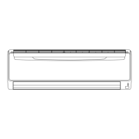
WALL MOUNTED TYPE
ASU2 4CL1
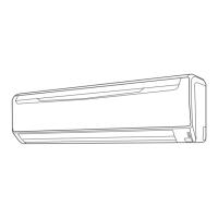
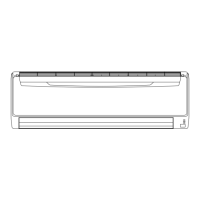
WALL MOUNTED TYPE
ASU2 4CL1
EXTERNAL INPUT & OUTPUT11.
Connector INPUT OUTPUT REMARKS
CN14
Control input
(Operation / stop)
-
See external
input/output settings
for details.
CN16 - Operation status output
EXTERNAL INPUT11-1.
CONTROL INPUT (Operation/Stop)
The air conditioner can be remotely operated by means of the following on-site work.
Operation is started at the following contents by adding the contact input of a commercial ON/OFF switch to a
connector on the external control PC board and turning it ON.
Initial starting after power turned on Starting other than at the left
Operation mode Auto changeover Mode at previous operation
Set temperature 75°F (24°C) Temperature at previous operation
Air ow mode AUTO Mode at previous operation
Up-down air direction (swing) Standard air direction (swing OFF) Air direction at previous operation
Left-right air direction (swing) Standard air direction (swing OFF) Air direction at previous operation
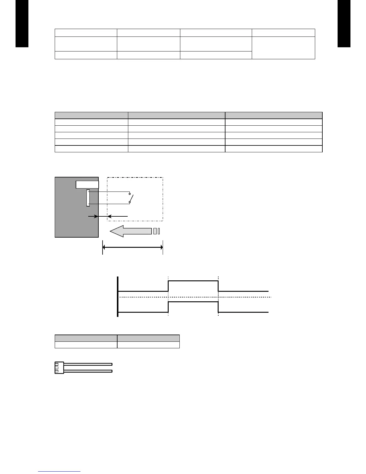
Circuit diagram example
z
Indoor
control PC board Connected unit
Ex.) Switch
Connector
1
3
Signal
Field supply
* Make the distance from the PC board to the connected unit within 33 ft. (10m).
Contact capacity : 5VDC or more, 20mA or more.
Please use the non-polar relays and switches.
*33 ft. (10 m)