Trouble shooting 3
INDOOR UNIT Error Method:
Detective Actuators: Detective details:
Forecast of Cause:
Check Point 2 : Check Wired Remote Controller and Controller PCB
Check Point 1 : Check the connection of terminal
OKOK
Indicate or Display:
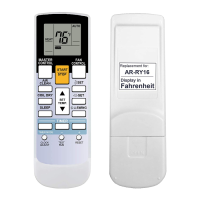
Wired Remote Controller
Communication Error
Indoor unit Controller PCB
Wired Remote Controller (Option)
1. Connection failure 2. Wired Remote Controller failure 3. Controller PCB failure
Check & correct the followings.
Check the connection of terminal between Wired Remote Controller and indoor unit,
and check if there is a disconnection of the cable.
When the indoor unit cannot properly receive the signal from
Wired Remote Controller for 1 minute or more.
02-06
Refer to error code table.
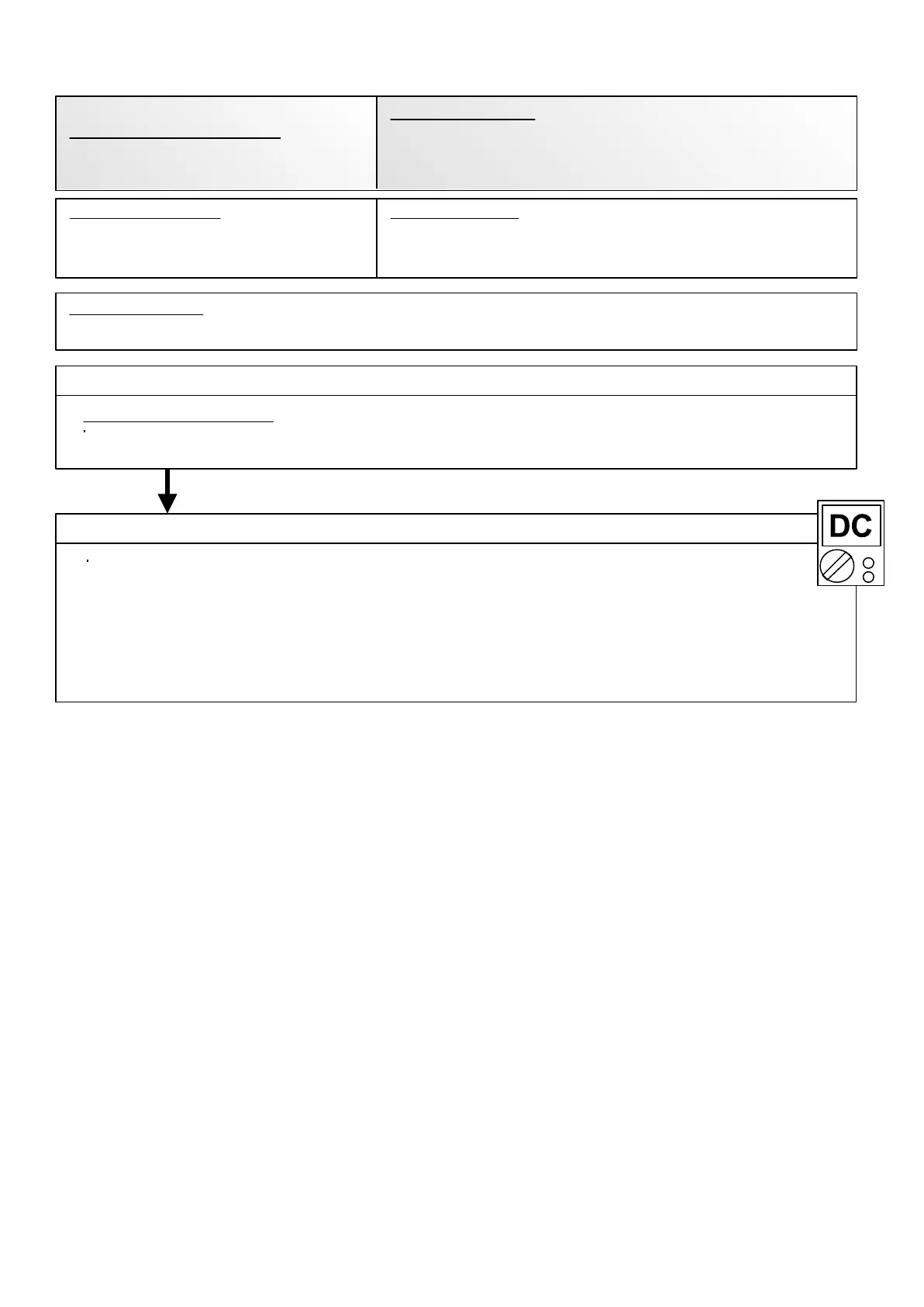
>> If it is DC12V, Remote Control is failure. (Controller PCB is normal) >> Replace Remote Control
>> If it is DC 0V, Controller PCB is failure. (Check Remote Control once again) >> Replace Controller PCB
Check Voltage at terminal 1-3 of Controller PCB or Communication PCB.
(Power supply to Remote Control)
Cassette, Duct Type : CN14
Wall mount Type : CN6
Compact Wall mount Type : CN305(UTY-XCBXZ1)
 Loading...