En-5
Pipe outside diameter
[in. (mm)]
Dimension A [in. (mm)]
Dimension B [in. (mm)]
Flare tool for R410A,
clutch type
1/4 (6.35)
0 to 0.020
(0 to 0.5)
3/8 (9.1)
3/8 (9.52)
1/2 (13.2)
1/2 (12.70)
5/8 (16.6)
5/8 (15.88)
3/4 (19.7)
3/4 (19.05)
15/16 (24.0)
When using conventional are tools to are R410A pipes, the dimension A should be
approximately 0.020 in. (0.5 mm) more than indicated in the table (for aring with R410A
flare tools) to achieve the specified flaring. Use a thickness gauge to measure the
dimension A.
Width across
flats
Pipe outside
diameter [in. (mm)]
Width across flats of
Flare nut [in. (mm)]
1/4 (6.35)
11/16 (17)
3/8 (9.52)
7/8 (22)
1/2 (12.70)
1 (26)
5/8 (15.88)
1-1/8 (29)
3/4 (19.05)
1-7/16 (36)
5.6.2. Bending pipes
• If pipes are shaped by hand, be careful not to collapse them.
• Do not bend the pipes in an angle more than 90°.
• When pipes are repeatedly bend or stretched, the material will harden, making it difcult
to bend or stretch them anymore.
• Do not bend or stretch the pipes more than 3 times.
CAUTION
• To prevent breaking of the pipe, avoid sharp bends.
• If the pipe is bent repeatedly at the same place, it will break.
5.6.3. Pipe connection
CAUTION
• Be sure to Install the pipe against the port on the indoor unit correctly. If the center-
ing is improper, the are nut cannot tighten smoothly. If the are nut is forced to
turn, the threads will be damaged.
• Do not remove the are nut from the indoor unit pipe until immediately before con-
necting the connection pipe.
• Hold the torque wrench at its grip, keeping it in the right angle with the pipe, in order
to tighten the are nut correctly.
• Tighten the are nuts with a torque wrench using the specied tightening method.
Otherwise, the are nuts could break after a prolonged period, causing refrigerant to
leak and generate hazardous gas if the refrigerant comes into contact with a ame.
CAUTION
• Connect the piping so that the control box cover can easily be removed for servicing
when necessary.
• In order to prevent water from leaking into the control box, make sure that the piping
is well insulated.
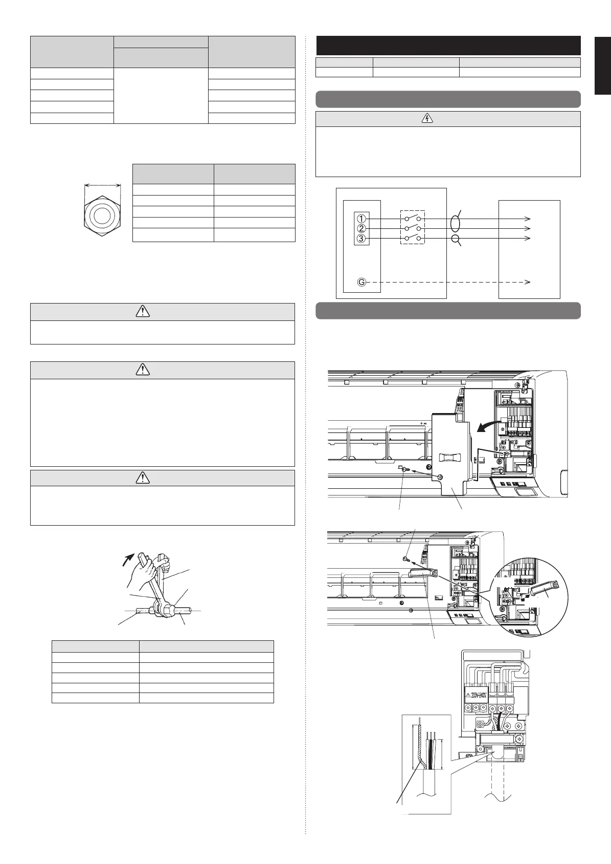
When the flare nut is tightened properly by your hand, hold the body side coupling with a wrench,
then tighten with a torque wrench. (See the table below for the flare nut tightening torques.)
Tighten with two wrenches.
Holding wrench
Flare nut
Connection pipe
Torque wrench
Indoor unit pipe
(Body side)
Flare nut [in. (mm)] Tightening torque [lb·ft (N·m)]
1/4 (6.35) dia. 11.8 to 13.3 (16 to 18)
3/8 (9.52) dia. 23.6 to 31.0 (32 to 42)
1/2 (12.70) dia. 36.1 to 45.0 (49 to 61)
5/8 (15.88) dia. 46.5 to 55.3 (63 to 75)
3/4 (19.05) dia. 66.4 to 81.1 (90 to 110)
6. ELECTRICAL WIRING
Cable Cable size Remarks
Connection cable 14AWG 3 cable+Earth (Ground), 1φ 208/230 V
Max. Cable Length: Limit voltage drop to less than 2%. Increase cable gauge if voltage drop is 2% or more.
6.1.
Wiring system diagram
WARNING
• Before connecting the wires, make sure the power supply is OFF.
• Every wire must be connected rmly.
•
No wire should be allowed to touch refrigerant tubing, the compressor or any moving part.
• Loose wiring may cause the terminal to overheat or result in unit malfunction. A re
hazard may also exist. Therefore, be sure all wiring is tightly connected.
• Connect wires to the matching numbers of terminals.
INDOOR UNIT SIDE
Earth (ground)
line
DISCONNECT
SWITCH
(Locally purchased)
OUTDOOR UNIT
Connect it to
the specied
terminal.
INDOOR UNIT
TERMINAL
Power line
Control line
6.2.
Indoor unit wiring
1. Remove the wire cover. (Remove 1 screw.)
2. Remove the cable clamp.
3. Ring terminals connect to the connection cable.
4. Connect the ring terminals fully into the terminal block.
5. Fasten the connection cable with a cable clamp.
6.
Insert the wire cover tab into the square hole of the indoor unit and fasten with a screw.
Screw
Wire cover
Screw
Cable clamp
Cable clamp
Hook
1 2 3
1 2 3
Earth (ground) wire
1 in. 25 mm
2.5 in. (65 mm)
9387082098-02_IM.indb 5 21/03/2016 10:12:53
 Loading...