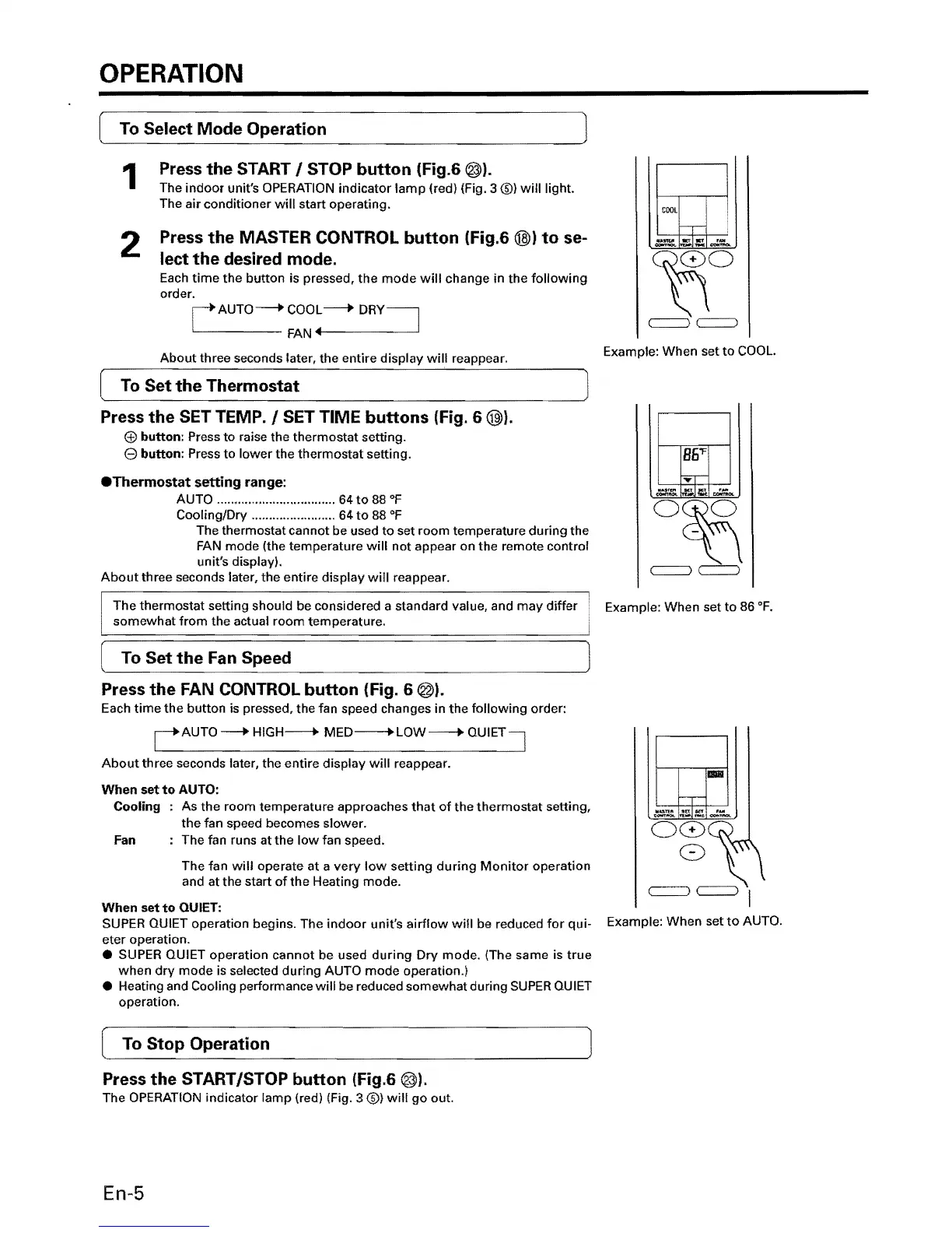
OPERATION
To
Select Mode Operation
Press
the
START /
STOP
button
(Fig.6 @).
1
The
indoor
unit's OPERATION
indicator
lamp
(red) (Fig. 3
®)
will
light.
The air
conditioner
will
start operating.
2
Press
the
MASTER CONTROL
button
(Fig.6
@»)
to
se-
lect
the
desired mode.
Each
time
the
button
is pressed,
the
mode
will
change in the
following
order.
rAUTO
----+
COOL
---J>
DRY
~
L-
____
FAN
....
------'
Example: When
set
to
COOL.
About
three seconds later, the
entire
display
will
reappear.
To
Set
the
Thermostat
Press
the
SET
TEMP./
SET
TIME
buttons
(Fig. 6
@»).
button:
Press
to
raise the
thermostat
setting.
e
button:
Press
to
lower
the
thermostat
setting.
.Thermostat
setting
range:
AUTO .................................. 64
to
88
OF
Cooling/Dry ........................ 64
to
88
OF
The thermostat
cannot
be used
to
set
room
temperature
during
the
FAN
mode
(the temperature
will
not
appear
on
the
remote
control
unit's display).
About
three seconds later,
the
entire
display
will
reappear.
B6'F
The
thermostat
setting should be considered a standard value, and
may
differ
Example:
When
set
to
86
OF.
somewhat
from
the actual
room
temperature.
To Set
the
Fan
Speed
Press
the
FAN CONTROL
button
(Fig. 6 @).
Each
time
the
button
is pressed, the fan speed changes in
the
following
order:
CAUTO----+
HIGH--+
MED----+LOW--+
QUIET"]
About
three seconds later, the
entire
display
will
reappear.
When
set
to
AUTO:
-
Cooling
As
the
room
temperature
approaches
that
of
the
thermostat
setting,
the
fan speed becomes slower.
Fan The fan runs at the
low
fan speed.
The
fan
will
operate
at
a
very
low
setting
during
Monitor
operation
and at the start
of
the
Heating
mode.
When
set
to
QUIET:
SUPER QUIET operation begins. The
indoor
unit's
airflow
will
be reduced
for
qui-
Example:
When
set
to
AUTO.
eter operation .
• SUPER QUIET
operation
cannot
be used
during
Dry
mode.
(The same is
true
when
dry
mode
is selected
during
AUTO
mode
operation.)
• Heating and Cooling performance
will
be reduced somewhat during
SUPER
QUIET
operation.
Press
the
START/STOP
button
(Fig.6 @).
The OPERATION indicator
lamp
(red) (Fig. 3 (0)
will
go
out.
En-5