EasyManua.ls Logo

Fujitsu ASY30LBA-W User Manual

Fujitsu ASY30LBA-W
23 pages
To Next Page IconTo Next Page
Page #1 background imageLoading...
Page #1 background image
SPLIT TYPE
ROOM AIR CONDITIONER
W A L L M O U N T E D
ty pe
CONTENTS
SPECIFICATIONS
. . . . . . . . . . . . . . . . . . . . . . . . . . . . . . . . 1
OUTLINE AND DIMENSIONS . . . . . . . . . . . . . . . . . . . . . . . . . . 3
REFRIGERANT SYSTEM DIAGRAM . . . . . . . . . . . . . . . . . . . . 4
ERROR CONTENTS . . . . . . . . . . . . . . . . . . . . . . . . . . . . . . . . . . 5
CIRCUIT DIAGRAM
. . . . . . . . . . . . . . . . . . . . . . . . . . . . . . . 6
INDOOR PRINTED CIRCUIT BOARD CIRCUIT DIAGRAM . . 7
OUTDOOR PRINTED CIRCUIT BOARD CIRCUIT DIAGRAM 8
DISASSEMBLY ILLUSTRATION . . . . . . . . . . . . . . . . . . . . . . . 12
PARTS LIST . . . . . . . . . . . . . . . . . . . . . . . . . . . . . . . . . . . . . . . 18
Models Indoor unit Outdoor unit
ASY24LBA-W AOY24LMAL
ASY30LBA-W AOY30LMAL
STANDARD ACCESSORIES . . . . . . . . . . . . . . . . . . . . . . . . . . . 20
Question and Answer IconNeed help?

Do you have a question about the Fujitsu ASY30LBA-W and is the answer not in the manual?

Fujitsu ASY30LBA-W Specifications

General IconGeneral
BrandFujitsu
ModelASY30LBA-W
CategoryAir Conditioner
LanguageEnglish

Summary

SPECIFICATIONS

Electrical Data, Compressor, Fan Motor, Dimensions, Weight

Electrical, compressor, fan motor, dimensions, and weight specifications.

Noise Level and Refrigerant Charge

Noise level and refrigerant charge specifications.

OUTLINE AND DIMENSIONS

REFRIGERANT SYSTEM DIAGRAM

ERROR CONTENTS

DIP Switch Settings

Settings for the DIP switch for model configuration.

CIRCUIT DIAGRAM

Indoor Printed Circuit Board Circuit Diagram

Detailed circuit diagram for the indoor unit's printed circuit board.

Outdoor Printed Circuit Board Circuit Diagram

Detailed circuit diagram for the outdoor unit's printed circuit board.

Outdoor Unit Controller PCB Assembly Circuit Diagram

Circuit diagram for the outdoor unit's controller PCB assembly.

Power Supply PCB Assembly Circuit Diagram

Circuit diagram for the power supply PCB assembly.

TR PCB Assembly Circuit Diagram

Circuit diagram for the TR PCB assembly.

DISASSEMBLY ILLUSTRATION

PARTS LIST

Indoor Unit Parts

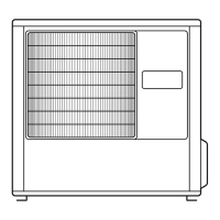
List of replacement parts for the indoor unit.

Outdoor Unit Parts

List of replacement parts for the outdoor unit.

STANDARD ACCESSORIES

Indoor Unit Accessories

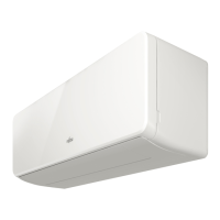
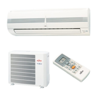
Standard accessories included with the indoor unit.

Outdoor Unit Accessories

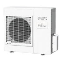
Standard accessories included with the outdoor unit.

Thermistor Resistance Values

Room Temperature Thermistor (THIA)

Resistance values for the room temperature thermistor.

Indoor Heat Exchanger Temperature Thermistor (THHM, THHI)

Resistance values for the indoor heat exchanger thermistor.

Related product manuals