¢
External output
Use an external output cable with appropriate external dimension, depending on the number of ca-
bles to be installed.
External Input and Output PCB
• A twisted pair cable (22AWG) should be used. Maximum length of cable is 25 m.
• Output voltage: High DC 12 V±2 V, Low 0 V.
• Permissible current: 50 mA
• For details, refer to
"Combination of external input and output" on page 207.
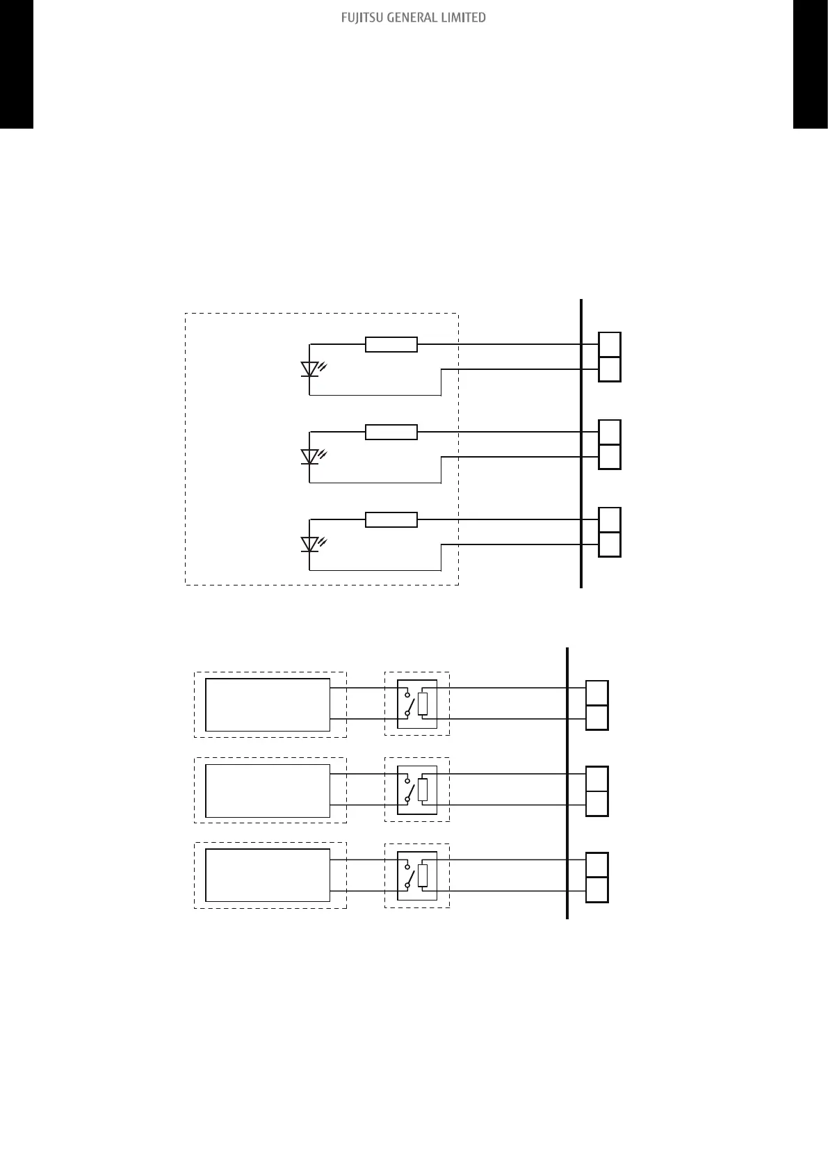
• When indicator or other components are connected directly:
Example: Function setting 60 is set to "00".
Connector
(CN310)
LED 1
(Operation status)
PCB
Resistor
Connected unit
+
-
Connector
(CN311)
LED 2
(Error status)
Resistor
+
-
Connector
(CN312)
LED 3
(Indoor unit fan
operation status)
Resistor
+
-
• When connecting with a device equipped with a power supply:
Example: Function setting 60 is set to "00".
1
2
Connected device 1
Connector
(CN310)
PCBConnected unit
Relay
(Operation status)
-
+
1
2
Connected device 2
Connector
(CN311)
(Error status)
-
+
1
2
Connected device 3
Connector
(CN312)
(Indoor unit fan
operation status)
-
+
- 206 -
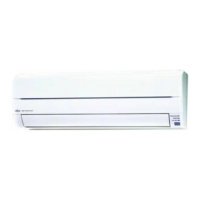
12-3. Wall mounted type (KGTB, 18-24KMTB, KETA, and KETA-B)
12. External input and output
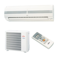
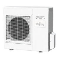
4-5 UNIT
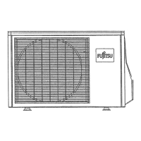
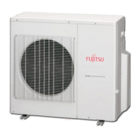
MULTI-SPLIT TYPE
4-5 UNIT
MULTI-SPLIT TYPE
 Loading...