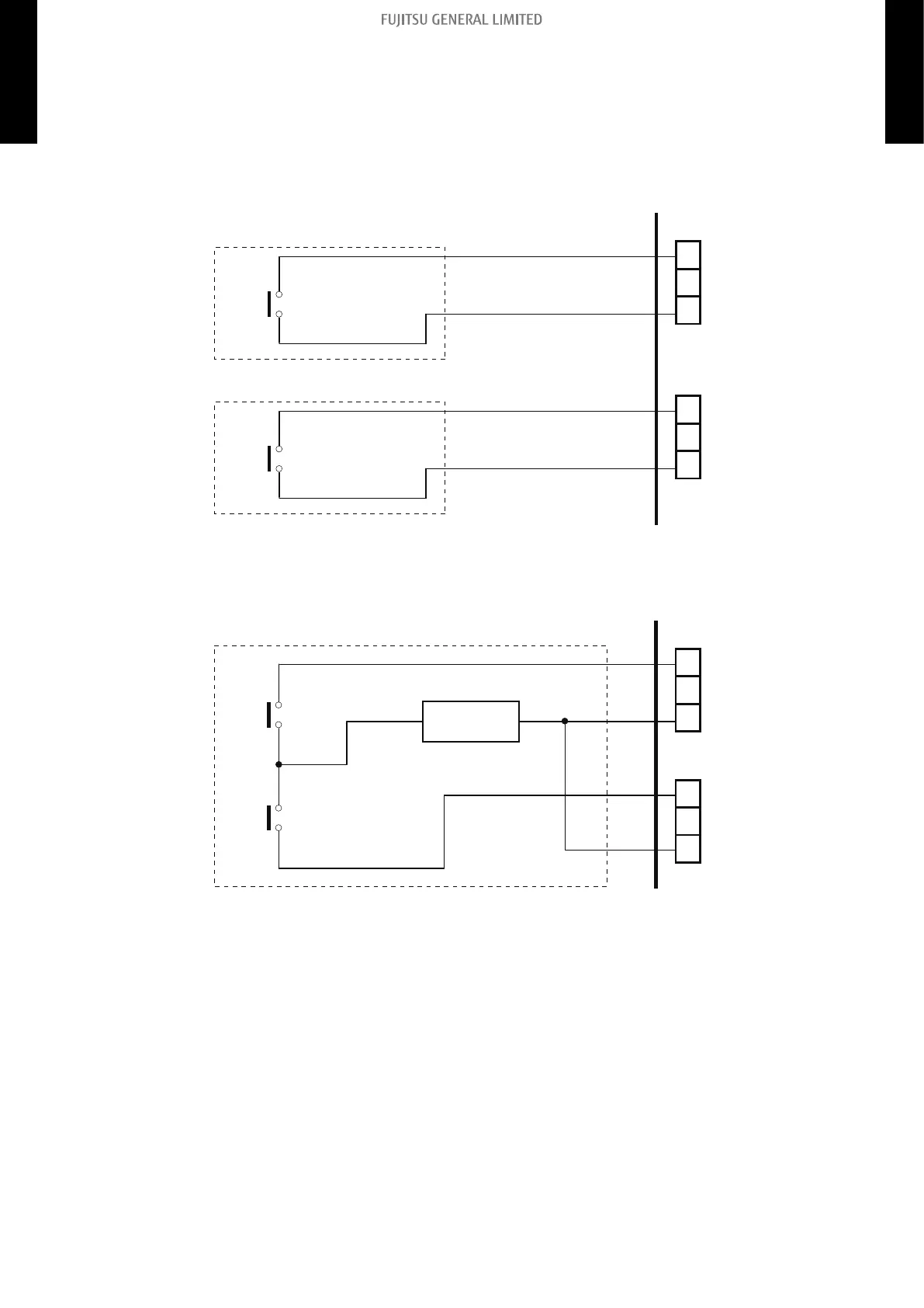
External Input and Output PCB
The indoor unit Operation/Stop can be set by using the input connector on the PCB.
• Input select:
Use either one of these types of connectors according to the application. (Both types of connec-
tors cannot be used simultaneously.)
– Dry contact
In case of internal power supply, set the slide switch of SW301 to "NON VOL" side.
Input 1
PCB
Connected unit
*
+
-
Input 2
*
+
-
Connector
(CN313)
Connector
(CN314)
*1: The switches can be used on the following condition: DC 12 V to 24 V, 1 mA to 15 mA.
– Apply voltage
In case of external power supply, set the slide switch of SW301 to "VOL" side.
Input 1
Power supply
PCB
Connected unit
*
*
*2
+-
Input 2
Connector
(CN313)
Connector
(CN314)
*1: The switches can be used on the following condition: DC 12 V to 24 V, 1 mA to 15 mA.
*2: Make the power supply DC 12 to 24 V, 10 mA or more.
- 221 -
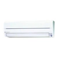
12-5. Wall mounted type (KGTE, KGTF, KMTE, KMCE, KMCF, KETE, KETE-B, KETF, and
KETF-B)
12. External input and output
4-5 UNIT
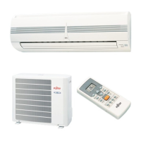
MULTI-SPLIT TYPE
4-5 UNIT
MULTI-SPLIT TYPE
 Loading...