¢
External Input and Output PCB
• A twisted pair cable should be used. Maximum length of cable is 25 m.
• Output voltage: High DC 12 V ±2 V, Low 0 V.
• Permissible current: 50 mA
• For details, refer to "Setting of external input and output" on page 05-15.
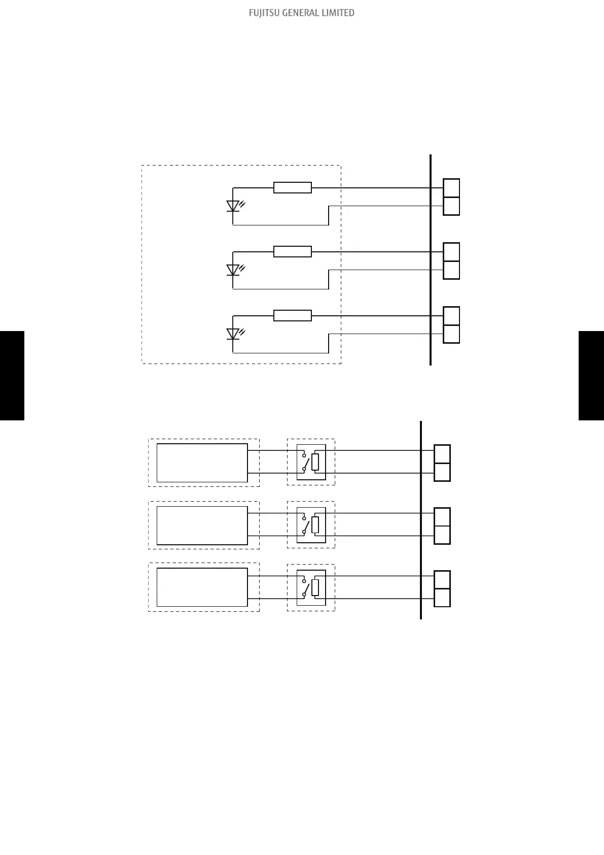
• When indicator or other components are connected directly:
Example: Rotary SW on External Input and Output PCB is set to “1”.
CN310
LED 1
(Operation status)
PCB
Resistor
Connected device
+
-
CN311
LED 2
(Error status)
Resistor
+
-
CN312
LED 3
(Indoor unit fan
operation status)
Resistor
+
-
• When connecting with a device equipped with a power supply:
Example: Rotary SW on External Input and Output PCB is set to “1”.
1
2
Connected device 1
CN310
PCB
Connected device Relay
(Operation status)
-
+
1
2
Connected device 2
CN311
(Error status)
-
+
1
2
Connected device 3
CN312
(Indoor unit fan
operation status)
-
+
2-2. External output - (05-14) - 2. External input and output
FIELD
WORKING
FIELD
WORKING
 Loading...