EasyManua.ls Logo

Fujitsu ASYG09LLCA - User Manual

Fujitsu ASYG09LLCA
25 pages
To Next Page IconTo Next Page
Loading...
SPLIT TYPE
ROOM AIR CONDITIONER
WALL MOUNTED TYPE
CONTENTS
SPECIFICATIONS. . . . . . . . . . . . . . . . . . .
1
DIMENSIONS . . . . . . . . . . . . . . . . . . . . . .
2
REFRIGERANT SYSTEM DIAGRAM. . . .
3
CIRCUIT DIAGRAM . . . . . . . . . . . . . . . . .
4
ERROR DETECTION . . . . . . . . . . . . . . .
5
INDOOR PCB CIRCUIT DIAGRAM . . . . .
9
OUTDOOR PCB CIRCUIT DIAGRAM . . .
13
PARTS (INDOOR UNIT) . . . . . . . . . . . . .
14
PARTS (OUTDOOR UNIT) . . . . . . . . . . .
19
23
ACCESSORIES . . . . . . . . . . . . . . . . . . .
Indoor unit Outdoor unit
ASYG09LLCA
ASYG12LLCA
AOYG09LLC
AOYG12LLC
Question and Answer IconNeed help?

Do you have a question about the Fujitsu ASYG09LLCA and is the answer not in the manual?

Fujitsu ASYG09LLCA Specifications

General IconGeneral
TypeSplit System
Cooling Capacity2.5 kW
Heating Capacity3.2 kW
Energy Efficiency Rating (Cooling)A++
Energy Efficiency Rating (Heating)A+
RefrigerantR32
Power Supply220-240 V, 50 Hz
Weight (Indoor Unit)8 kg
Indoor Unit Noise Level21 dB(A) (Low)
Coefficient of Performance (COP)4.00

Summary

SPECIFICATIONS

ELECTRICAL DATA

Electrical properties of the air conditioner units for cooling and heating.

NOISE LEVEL

Sound pressure levels for indoor and outdoor units during operation.

COMPRESSOR AND REFRIGERANT

Details on compressor type, refrigerant type, and charging specifications.

FAN MOTOR SPECIFICATIONS

Specifications for indoor and outdoor unit fan motor speeds at different operation modes.

WEIGHT SPECIFICATIONS

Net and shipping weights for indoor and outdoor units.

DIMENSIONS

INDOOR UNIT DIMENSIONS

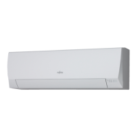
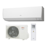
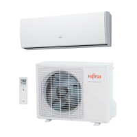
Detailed measurements and diagrams for the indoor unit.

OUTDOOR UNIT DIMENSIONS

Detailed measurements and diagrams for the outdoor unit.

REFRIGERANT SYSTEM DIAGRAM

REFRIGERANT FLOW DIAGRAM (09 Model)

Illustrates refrigerant path for the ASYG09/AOYG09 models.

REFRIGERANT FLOW DIAGRAM (12 Model)

Illustrates refrigerant path for the ASYG12/AOYG12 models.

INDOOR UNIT CIRCUIT DIAGRAM

MAIN PCB CIRCUIT

Electrical schematic for the indoor unit's main circuit board.

INDOOR PCB CIRCUIT DIAGRAM

INDOOR UNIT INDICATOR PCB CIRCUIT DIAGRAM

OUTDOOR UNIT PCB CIRCUIT DIAGRAM

OUTDOOR UNIT MAIN PCB SCHEMATIC

ERROR DETECTION

TROUBLESHOOTING GUIDE

Table listing errors, operation, and timer lamp codes for troubleshooting.

INDOOR UNIT PARTS OVERVIEW

REMOTE CONTROL

Part number for the remote control unit.

FRONT PANEL ASSEMBLY

Part number for the front panel assembly including air filter.
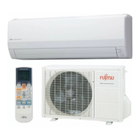
OUTDOOR UNIT PARTS OVERVIEW

OUTDOOR UNIT ELECTRONIC COMPONENTS

Related product manuals