En-9
Accessories (Communication kit)12. 1.
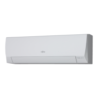
The following installation accessories are supplied. Use them as required.
Name and Shape
Q’ty
Description
Relay control board
1
For connecting the
wired remote control
unit and external
connect wire.
Binder
1
For Þ xing the wires
from control box.
Relay wire
1
For connecting the
relay control board and
control unit board.
Wiring label
1
For display the additional
wiring diagram.
Installation work12. 2.
12.2.1. Removing intake grille and front panel
(Refer to 9.1. Intake grille removal and 9.3. Front panel removal)
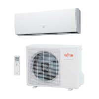
12.2.2. Removing control cover, connector and control box
Screw 1
Screw 2
Control cover
Ground wire (Green)
Control box
Screw 3
CN5 (White connector)
CN4 (Red connector)
CN14 *1.
(White connector)
CN7
(White connector)
Connector wires
(CN4, CN5, CN7, CN14)
(1) Remove the screw 1 then remove the control cover.
(2) Remove the connector wires.
*1. When there is CN14 connector, pull it out.
(3) Remove the connecting cables and the screw 2 and 3, then remove the control box.
12.2.3. Installing relay control board and relay wire terminal
Control unit board
Connector (CN8)
Relay wire
Notice *2.
Clasp
Connector (CND01)
Relay control board
Clasps
*2. Notice the installing direction
of the relay control board. (The
elevation of the control box is
fit for the recess of the relay
control board.)
(1) Insert the relay control board toward 2 clasps.
(2) Then set the board with the clasp.
(3) Connect the relay wire terminal to the connector (CND01) on the relay control board.
(4) Connect the relay wire terminal to the connector (CN8) on the control unit board.
CAUTION
Be careful not to damage the parts on the board.
Otherwise, it will cause malfunction.
12.2.4. Installing option kit
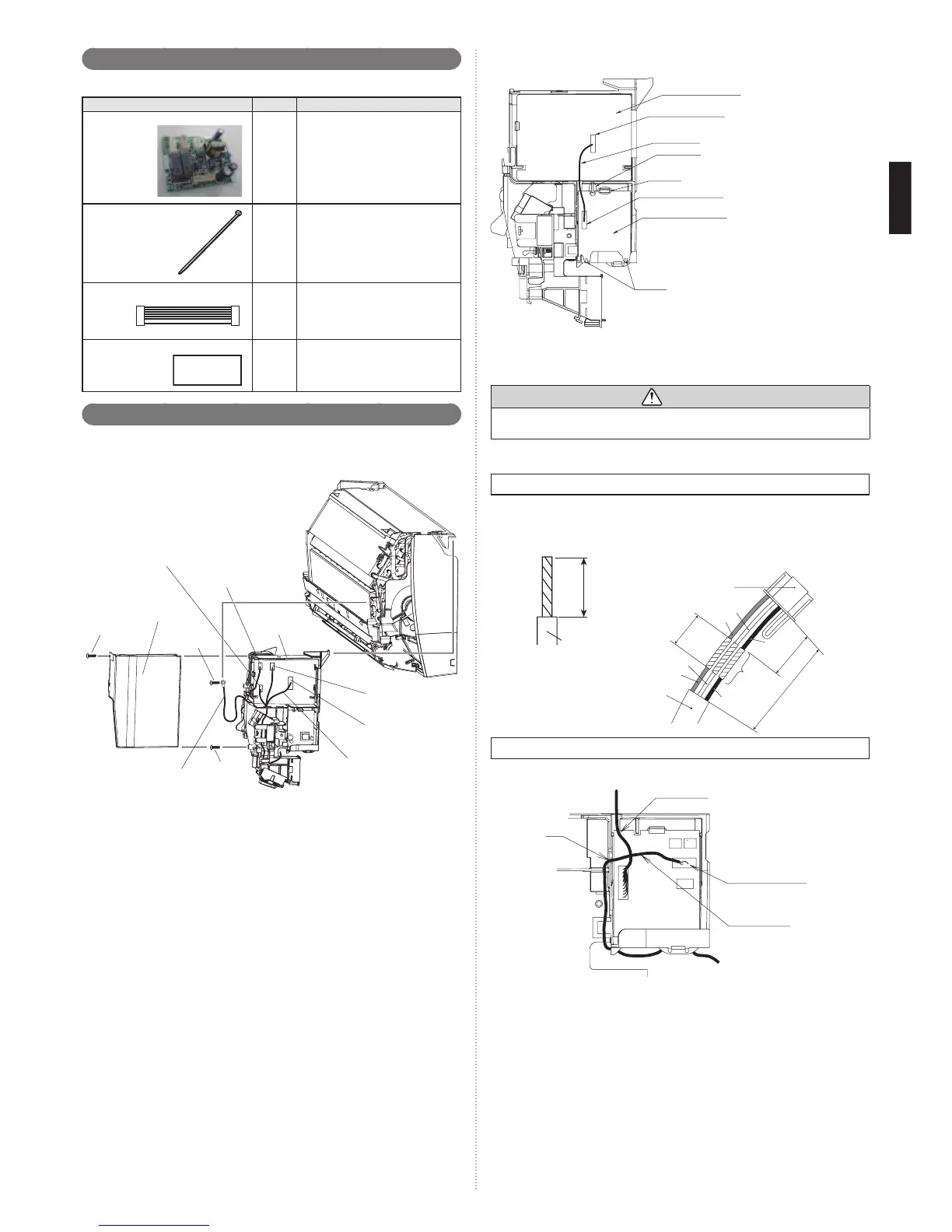
Remote controller cord modiÞ cation
(1) Use a tool to cut off the terminal on the end of the remote controller cord, and then
remove the insulation from the cut end of the cord.
(2) Connect the remote controller cord and connecting cord.
(Supplied with wired remote controller.)
Important: Be sure to insulate the connection between the cords.
20 mm
Remote
controller cord
Remote
controller cord
Red
Red
White
White
Black
Black
Insulated
connection
Connector
30 mm
35 ~ 45 mm
70 ~80 mm
Installing the wired remote controller terminal (sold separately)
Connect the wired remote controller terminal to the connector
(CNC01) on the relay control board.
Relay wire
Connector : CNC01
Wired remote
controller cord
Rib
 Loading...