EasyManua.ls Logo

Fujitsu AUYA45LCLU User Manual

Fujitsu AUYA45LCLU
34 pages
To Next Page IconTo Next Page
Page #1 background imageLoading...
Page #1 background image
SPLIT TYPE
AIR CONDITIONER
CASSETTE TYPE (50Hz)
Indoor unit Outdoor unit
AUYA45LCLU
AUYA54LCLU
AOYA45LCTL
AOYA54LCTL
CONTENTS
SPECIFICATIONS
. . . . . . . . . . . . . . . . . . . .
1
DIMENSIONS
. . . . . . . . . . . . . . . . . . . . . . .
2
REFRIGERANT SYSTEM DIAGRAM
. . . . .
4
CIRCUIT DIAGRAM
. . . . . . . . . . . . . . . . . . .
5
ERROR DETECTION
. . . . . . . . . . . . . . . . .
6INDOOR PCB CIRCUIT DIAGRAM
. . . . . .
. . . .
10OUTDOOR PCB CIRCUIT DIAGRAM
16
PARTS (INDOOR UNIT)
. . . . . . . . . . . . . .
21
PARTS (OUTDOOR UNIT)
. . . . . . . . . . . .
28
ACCESSORIES
. . . . . . . . . . . . . . . . . . . . .
31
Question and Answer IconNeed help?

Do you have a question about the Fujitsu AUYA45LCLU and is the answer not in the manual?

Fujitsu AUYA45LCLU Specifications

General IconGeneral
BrandFujitsu
ModelAUYA45LCLU
CategoryAir Conditioner
LanguageEnglish

Summary

SERVICE MANUAL

SPECIFICATIONS OVERVIEW

ELECTRICAL DATA

Detailed electrical specifications for cooling and heating performance.

NOISE LEVEL

Noise level measurements for indoor and outdoor units in different modes.

COMPRESSOR AND REFRIGERANT

Details on the compressor type and refrigerant specifications.

FAN MOTOR SPECIFICATIONS

Specifications for indoor and outdoor unit fan motor speeds.

UNIT DIMENSIONS

Physical dimensions of the indoor and outdoor units.

UNIT WEIGHT

Weight specifications for indoor and outdoor unit components.

INDOOR UNIT DIMENSIONS

INDOOR UNIT DETAIL

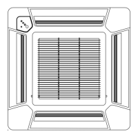
Detailed dimensional drawings and measurements for the indoor unit.

OUTDOOR UNIT DIMENSIONS

REFRIGERANT SYSTEM DIAGRAM

OUTDOOR UNIT REFRIGERANT FLOW

Diagram illustrating the refrigerant flow within the outdoor unit.

INDOOR UNIT REFRIGERANT FLOW

Diagram illustrating the refrigerant flow within the indoor unit.

CIRCUIT DIAGRAMS

OUTDOOR UNIT CIRCUIT

Electrical circuit diagram for the outdoor unit components.

INDOOR UNIT CIRCUIT

Electrical circuit diagram for the indoor unit components.

INDOOR PCB CIRCUIT DIAGRAM

INDOOR CONTROL UNIT CIRCUIT

Circuit diagram for the indoor unit's control and power supply PCBs.

INDOOR-OUTDOOR UNIT CONNECTIONS

Connections between indoor and outdoor units shown in the circuit diagram.

REMOTE CONTROL UNIT WIRING

Wiring diagram for the remote control unit connection.

INDOOR UNIT CONTROLLER PCB

CONTROLLER PCB ASSEMBLY (MAIN PCB)

Detailed circuit schematic of the main controller PCB for the indoor unit.

INDOOR UNIT POWER SUPPLY PCB

POWER SUPPLY PCB ASSEMBLY

Circuit schematic for the indoor unit's power supply PCB.

INDOOR UNIT INDICATOR PCB

INDICATOR PCB ASSEMBLY (OPTION)

Circuit diagram for the optional indicator PCB assembly.

OUTDOOR PCB CIRCUIT DIAGRAM

INVERTER ASSEMBLY CIRCUIT

Circuit diagram for the outdoor unit's inverter assembly.

OUTDOOR UNIT MAIN CIRCUIT

Overall connections for the outdoor unit's circuit diagram.

OUTDOOR CONTROLLER PCB CIRCUIT

Circuit diagram for the outdoor unit's main controller PCB.

OUTDOOR UNIT PCB ASSEMBLY DETAILS

OUTDOOR PCB ASSEMBLY (MAIN PCB) - 1

Detailed circuit schematic of the outdoor main PCB, part 1.

OUTDOOR PCB ASSEMBLY (MAIN PCB) - 2

Detailed circuit schematic of the outdoor main PCB, part 2.

OUTDOOR UNIT TRANSISTOR PCB

TRANSISTOR PCB ASSEMBLY (IPM)

Circuit diagram for the outdoor unit's IPM transistor PCB assembly.

OUTDOOR UNIT INDICATOR PCB DIAGRAM

INDICATOR PCB ASSEMBLY

Circuit diagram for the outdoor unit's indicator PCB assembly.

OUTDOOR UNIT CAPACITOR PCB DIAGRAM

CAPACITOR PCB ASSEMBLY

Circuit diagram for the outdoor unit's capacitor PCB assembly.

ERROR DETECTION: REMOTE CONTROL

REMOTE CONTROL ERROR CODES

Troubleshooting errors displayed on the remote control LCD.

SELF-DIAGNOSIS CODES

Explanation of self-diagnosis error codes and displays.

INDOOR UNIT ERROR DISPLAY TROUBLESHOOTING

TROUBLESHOOTING INDOOR DISPLAY

How to interpret error indications on the indoor unit display.

ERROR DETECTION: OUTDOOR UNIT

OUTDOOR UNIT INDICATOR PCB ERRORS

Error codes indicated by LED blinking on the outdoor unit indicator PCB.

OUTDOOR UNIT TEST RUN PROCEDURE

TEST RUN METHODOLOGY

Procedure for setting up and performing a test run.

TEST RUN CHECKLIST

Key checks to perform during the outdoor unit test run.

OUTDOOR UNIT PUMP DOWN PROCEDURE

PUMP DOWN PREPARATION

Steps to prepare the unit for the pump down procedure.

PUMP DOWN PROCEDURE

Step-by-step instructions for performing the pump down operation.

PARTS: DECORATION PANEL

DECORATION PANEL UTG-UGYA-W PARTS

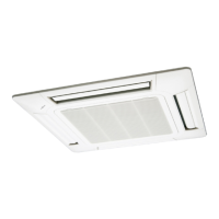
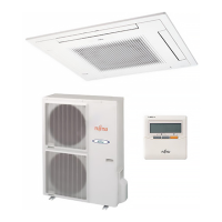
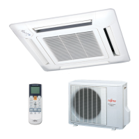
List and diagrams of parts for the decoration panel.

PARTS: INDOOR UNIT ASSEMBLY

INDOOR UNIT ASSEMBLY PARTS LIST

List and diagrams of parts for the indoor unit assembly.

PARTS: OUTDOOR UNIT ASSEMBLY

OUTDOOR UNIT ASSEMBLY PARTS LIST

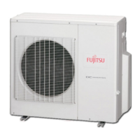
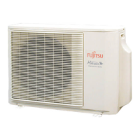
List and diagrams of parts for the outdoor unit assembly.

PARTS: OUTDOOR UNIT CONTROL BOX

OUTDOOR UNIT CONTROL BOX PARTS LIST

List and diagrams of parts for the outdoor unit control box.

ACCESSORIES LIST

INDOOR UNIT ACCESSORIES

List of accessories for the indoor unit installation.

DECORATION PANEL ACCESSORIES

List of accessories for the decoration panel.

OPTIONAL PARTS LIST

INDOOR UNIT OPTIONAL PARTS

Optional parts available for the indoor unit.

OUTDOOR UNIT OPTIONAL PARTS

Optional parts available for the outdoor unit.

Related product manuals