Do you have a question about the Fujitsu AUYG18LVLB and is the answer not in the manual?
Discusses system efficiency, seasonal efficiency, and compact design of outdoor units.
Covers installation patterns using branch box connection, large capacity connection, and long piping design.
Details easy installation aspects like branch box mounting directions and outdoor unit lightening.
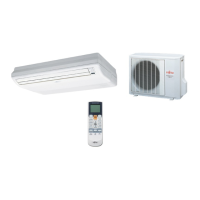
Explains various control options like wired, wireless, and central remote controllers.
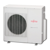
Details the model lineup for outdoor units and their model designation.
Lists indoor unit types, capacities, models, and model designation.
Lists and describes optional parts like branch boxes, separation tubes, and controllers.
Provides detailed specifications for the outdoor unit, including power, capacity, dimensions, and refrigerant.
Shows detailed dimensions for the outdoor unit and branch box with various views.
Details installation space requirements for outdoor units, including single and multiple unit installations.
Shows the refrigerant circuit diagram with symbols for components like compressors, heat exchangers, and valves.
Provides detailed wiring diagrams for outdoor units and branch boxes, illustrating connections.
Lists the operating temperature and humidity ranges for cooling and heating modes.
Presents noise level curves for the outdoor unit in cooling and heating modes across different frequencies.
Details electrical specifications for outdoor units and branch boxes, including power supply and wiring.
Lists safety devices for outdoor units and branch boxes, such as fuses, protectors, and protection circuits.
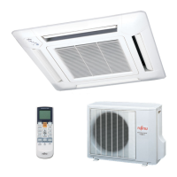
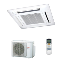
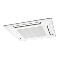
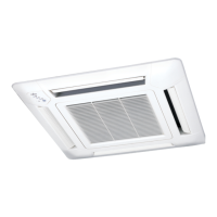
Highlights features of compact cassette indoor units, including a 2-stage turbo fan and easy maintenance.
Provides detailed specifications for compact cassette indoor units, covering dimensions, airflow, and electrical characteristics.
Shows electrical characteristics for various indoor unit types, including MCA, MFA, and FLA.
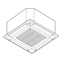
Illustrates dimensions for compact cassette indoor units, including top, side, and bottom views.
Presents wiring diagrams for compact cassette indoor units, showing connections to PCB and components.
Illustrates air velocity and temperature distributions for compact cassette indoor units in top and side views.
Displays fan performance curves for slim duct indoor units, showing static pressure vs. airflow for different modes.
Lists airflow rates (m³/h and CFM) for various indoor unit types and fan speeds in cooling and heating modes.
Shows noise level curves for compact cassette indoor units in cooling and heating modes, indicating NC levels.
Details safety devices for various indoor unit types, including PCB fuses, fan motor thermal protectors, and float switches.
Provides an overview of the control system, including controller lineup and design principles.
Lists available controllers such as central, wired, wireless, and simple remote controllers, detailing their features.
Illustrates the advanced integrated control system architecture, showing connections between units and controllers.
Provides examples of system configurations for individual and central control using various controller combinations.
Outlines design limitations for control equipment, specifying the number of connectable units per controller.
Shows images and identifies control units including central, wired, simple, and wireless remote controllers, and IR receiver units.
Details features of the central remote controller (UTY-DMM*M), including batch control and user-friendly operation.
Describes features of wired remote controllers (UTY-RVNM*, UTY-RNNM*), including auto-off timer and schedule timer functions.
Outlines features of the simple remote controller (UTY-RSNM), emphasizing easy operation, background light, and simple installation.
Details features of wireless remote controllers (AR-RAH2E/AR-RAH1E), including timer functions and custom code settings.
Explains the IR receiver unit (UTY-LRHM) for controlling duct type units with wireless remotes, including attachment and signal angle.
Describes the remote sensor unit (UTY-XSZX) for extending temperature sensing capabilities, including installation and wiring.
Illustrates methods for group control of remote controllers, showing combinations of wired, simple, and wireless types.
Compares functions of different controller types, including central, wired, simple, and wireless remote controllers.
Outlines the overall system design, showing the layout of outdoor units, branch boxes, indoor units, and controllers.
Provides a schematic of the system layout, indicating transmission lines, power supply, and piping.
Details connectable units within one refrigerant system, including capacity ratios and prohibited combinations.
Covers piping design aspects, including material, wall thickness, tools, and pipe size selection tables.
Highlights key considerations for R410A refrigerant, such as pressure, solubility, and necessary special tools.
Specifies limitations for piping, including total length, height difference, and branch box connections.
Provides tables for recommended pipe diameters and wall thicknesses based on nominal diameter and material.
Guides the selection of heat insulating material thickness based on relative humidity and pipe size.
Explains how to calculate additional refrigerant charge based on pipe length, using provided formulas and tables.
Shows examples of piping design, including capacity ratio calculation and selection of separation tubes and branch boxes.
Covers installation procedures, including opening knockout holes and performing pipe connections for outdoor units.
Details precautions for electrical wiring, emphasizing safety and compliance with local rules and regulations.
Provides precautions for electrical wiring, including power connection, cable fastening, and earth leakage breaker installation.
Explains power supply cable specifications and wiring for outdoor units, branch boxes, and indoor units.
Outlines transmission wiring specifications and limitations for connecting various system components.
Describes how to set functions for the outdoor unit using push buttons and 7-segment LED displays.
Explains the procedure for checking the system status, including precautions and itemized steps for a successful check run.
Lists general precautions for indoor unit installation, covering prohibited locations and specific considerations.
Details the specifications and dimensions of the separation tube (Model: UTP-SX248A), including port diameters and heat insulation.
Shows dimensions and types of branch boxes (UTP-PY03A: 3 branches, UTP-PY02A: 2 branches) with mounting options.
Lists applicable control methods for different indoor unit types, showing compatibility with central, wired, wireless, and simple controllers.
Provides a lineup of other optional parts, including cassette grilles, air outlet shutters, and communication kits.
| Cooling Capacity | 5.0 kW |
|---|---|
| Heating Capacity | 6.0 kW |
| Energy Efficiency Ratio (EER) | 3.21 |
| Energy Efficiency Ratio (Cooling) | 3.21 |
| Refrigerant | R32 |
| Outdoor Unit Dimensions (W x H x D) | 790 x 620 x 290 mm |
| Weight (Indoor Unit) | 13 kg |
| Power Supply | 220-240V, 50Hz |
| Noise Level (Indoor) | 42 dB(A) |
| Noise Level (Outdoor) | 52 dB(A) |
| Type | Split System |