Do you have a question about the Fujitsu AUYG12LVLA and is the answer not in the manual?
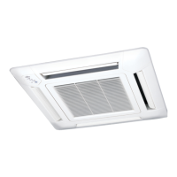
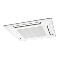
Details features like high efficiency, compact design, and innovative technology for the system.
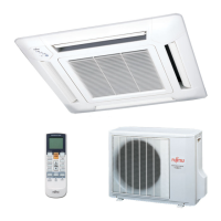
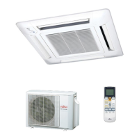
Describes wired and wireless remote controllers for easy operation and system control.
Outlines the step-by-step process for selecting indoor units, branch boxes, and controllers.
Presents the range of outdoor and indoor units available for system configuration.
Explains the procedure for selecting indoor and outdoor units based on capacity load.
Provides cooling capacity tables for outdoor units under various conditions.
Details compensation coefficients for pipe length and frosting/defrosting effects.
Presents cooling capacity tables for various indoor unit types.
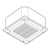
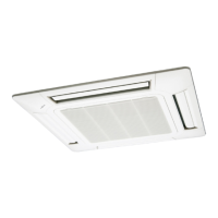
Illustrates wiring diagrams for compact cassette indoor units, showing connections to various components.
Presents wiring diagrams for slim duct indoor units, including connections to fan motors and control boards.
Shows wiring diagrams for wall-mounted indoor units, detailing connections to control boards and sensors.
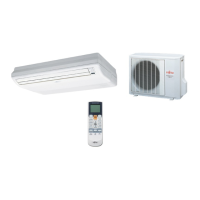
Illustrates wiring diagrams for floor/ceiling indoor units, including connections to display boards and fan motors.
Provides wiring diagrams for floor-type indoor units, showing connections to control boards and fan motors.
Details the features of central, wired, simple, and wireless remote controllers, including IR receiver units.
Describes the features of the central remote controller, including batch control and user-friendly operation.
Details the functions and features of wired remote controllers, including timer and auto-return settings.
Covers features of wireless remote controllers, including timer functions, custom codes, and operational modes.
Details connectable units within a refrigerant system, including quantity and capacity limitations.
Covers important items for R410A refrigerant piping, including material, wall thickness, and tools.
Specifies limitations for piping length, height difference, and pipe size to ensure correct operation.
Details installation procedures for outdoor units, including opening knockout holes and pipe connections.
Explains installation procedures for branch boxes, including unit mounting and control box positioning.
Provides precautions for electrical wiring, including regulations and safety measures.
Details power supply cable specifications and wiring examples for outdoor units, branch boxes, and indoor units.
Specifies transmission wiring specifications and limitations for connecting various system components.
Describes how to set functions for the outdoor unit using push buttons and DIP switches.
Guides on setting functions for indoor units using wireless remote controllers, including custom code selection.
Details setting functions for indoor units using wired remote controllers, including mode and timer settings.
Describes the procedure for performing a check run to verify system status and wiring.
Lists check run items, procedures, and error occurrences for troubleshooting.
Provides guidance on drain work for outdoor and indoor units to prevent water leakage.
| Heating Capacity | 4.0 kW |
|---|---|
| Power Supply | 220-240V, 50Hz |
| Weight (Indoor Unit) | 9 kg |
| Indoor Unit Weight | 9 kg |
| Outdoor Unit Noise Level | 48 dB(A) |