Do you have a question about the Fujitsu AUYG09LVLA and is the answer not in the manual?
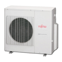
Lists available outdoor units, their capacities, model names, and connectable indoor unit ranges.
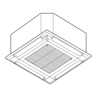
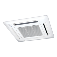
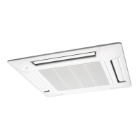
Details various indoor unit types, capacities, model codes, and their respective cooling/heating ratings.
Outlines the procedure for selecting indoor and outdoor units and performing capacity calculations for system design.
Provides detailed cooling and heating capacity tables for outdoor units based on various operating conditions.
Explains compensation coefficients for pipe length and frosting/defrosting to adjust system capacity accurately.
Presents cooling and heating capacity tables for various indoor unit types across different operating conditions.
Details technical specifications for the outdoor unit, including power, dimensions, refrigerant, and operation range.
Illustrates the refrigerant circuit diagram, showing connections between outdoor units, branch boxes, and indoor units with symbol descriptions.
Provides wiring diagrams for outdoor units and branch boxes, detailing electrical connections and terminal layouts.
Details safety devices and their ratings for outdoor units and branch boxes, such as fuses, protectors, and pressure switches.
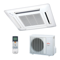
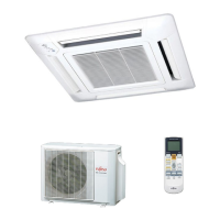
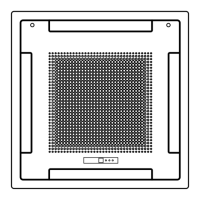
Lists detailed specifications for compact cassette indoor units, including model, power, airflow, sound pressure, and dimensions.
Provides wiring diagrams for compact cassette indoor units, illustrating connections for fan motor, control board, and sensors.
Lists safety devices for various indoor unit types, including PCB fuse, fan motor protector, thermal fuse, and float switch.
Lists available controllers such as central, wired, simple, and wireless remote controllers, with their features.
Illustrates the advanced integrated control system architecture, showing connections between outdoor, indoor units, branch boxes, and controllers.
Details the features and functions of the central remote controller (UTY-DMM*M), including its user-friendly interface and installation.
Covers important items for using R410A refrigerant, including piping material, wall thickness, lubricant, and necessary tools.
Details the outdoor unit installation process, focusing on opening knockout holes and performing pipe connections with correct procedures.
Outlines precautions for electrical wiring, emphasizing safety measures and adherence to local regulations for wire diameter and circuit breakers.
Explains the procedure for performing a check run to automatically verify the status of outdoor units and detect wiring mistakes.
Provides essential cautions regarding refrigerant leakage, concentration limits, and measures to take when the limit is exceeded.
| Cooling Capacity | 2.5 kW |
|---|---|
| Heating Capacity | 3.2 kW |
| Voltage (V) | 220-240V |
| Refrigerant | R32 |
| Cooling Capacity (BTU/hr) | 8530 BTU/hr |
| Heating Capacity (BTU/hr) | 10920 BTU/hr |
| EER | 3.55 |
| SEER | 6.6 |
| HSPF | 4.1 |
| Power Supply | 220-240 V |