Do you have a question about the Fujitsu AUYF12LAL and is the answer not in the manual?
| Cooling Capacity | 3.5 kW |
|---|---|
| Heating Capacity | 4.0 kW |
| Power Supply | 220-240V, 50Hz |
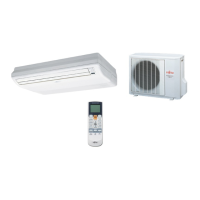
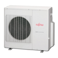
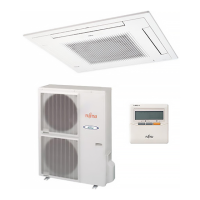
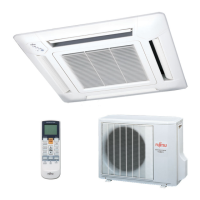
| Type | Split System |
| Refrigerant | R410A |
Detailed electrical specifications including voltage, current, and power consumption.
Illustrates the electrical connections and components for the indoor unit.
Shows circuit diagrams for indoor units AUYF18LBL and AUYF24LBL.
Details the wiring and connections for the indoor unit's control unit.
Provides the circuit diagram for the indoor unit's controller PCB assembly.
Lists error codes for the indoor unit and explains the operation/timer/filter lamp status.
Details error codes for the outdoor unit and their corresponding LED blinking patterns.