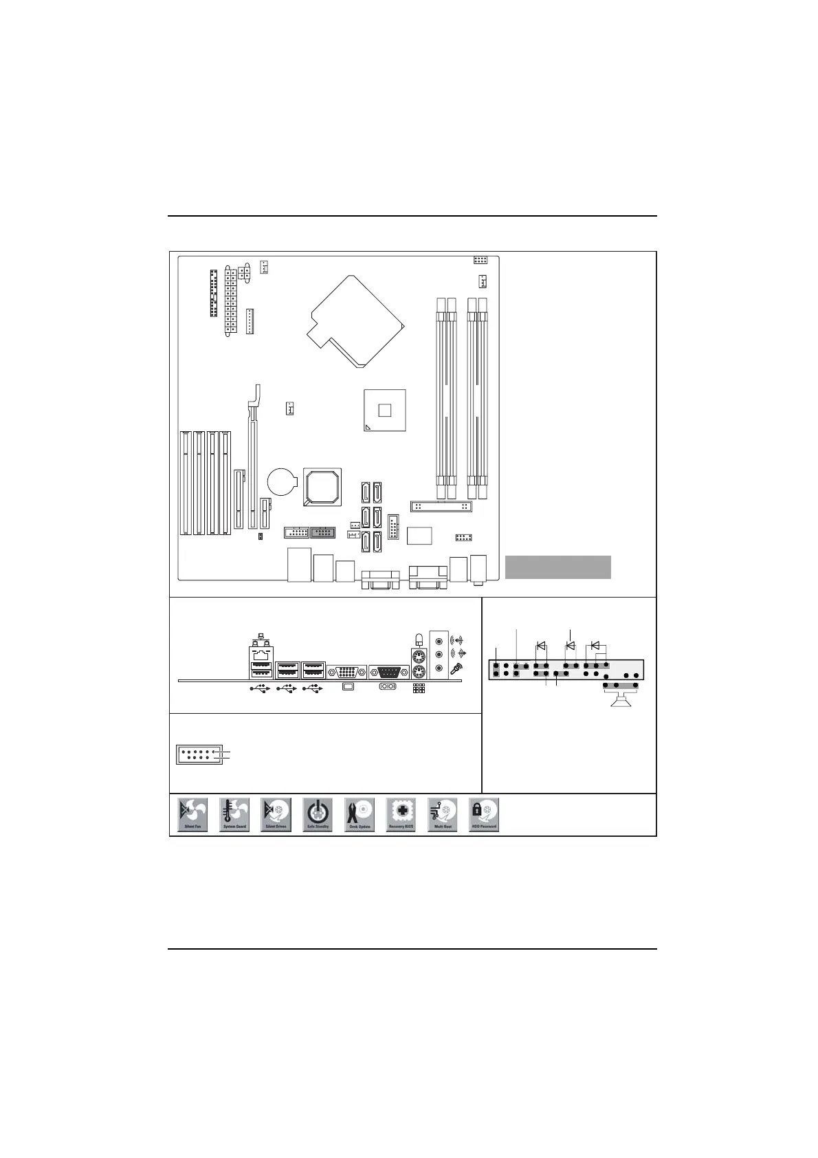
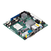
Mainboard D2317 - Internal co nn ecto r s and slots
Optionale Komponenten /
Optional components
External connectors rear
USB dual channel
Pin 2
Pin 1
PCI3
PCI2
PCI1
PCI4
PCI e x16
Frontpanel
Power
supply
control
PCI e x4
PCI e x1
Battery
Fan 1
Fan 3
Fan 2
Additional power supply
SATA2 SATA1
SATA4 S ATA 3
SATA5SATA6
Intrusion
USB
Floppy disk drive
1
3
2
4
Front Audio
USB
TPM
COM2
Fan 4
1 = Key
3 = VCC AUX
5 = Data negative Port X
4 = VCC AUX
2 = Not connected
7 = Data positive Port X
9 = GND
11 = Key
10 = GND
6 = Data negative Port Y 12 = Not connected
8 = Data positive Port Y
Channel B
Channel A
LCD-Display
Front panel
1) Both connector positions possible
2) 2pin or 3pin connector possible
1
2
HD-LED
Power On/Off
Recovery Password
1)
Message LED
Reset
Power On LED
2)
Speaker
Recovery inserted = The system starts
from floppy and allows a BIOS recovery
Password inserted = System- and BIOS
Password are skipped when device is
switched on
A26361-D2317-Z110-1-8N19, edition 2