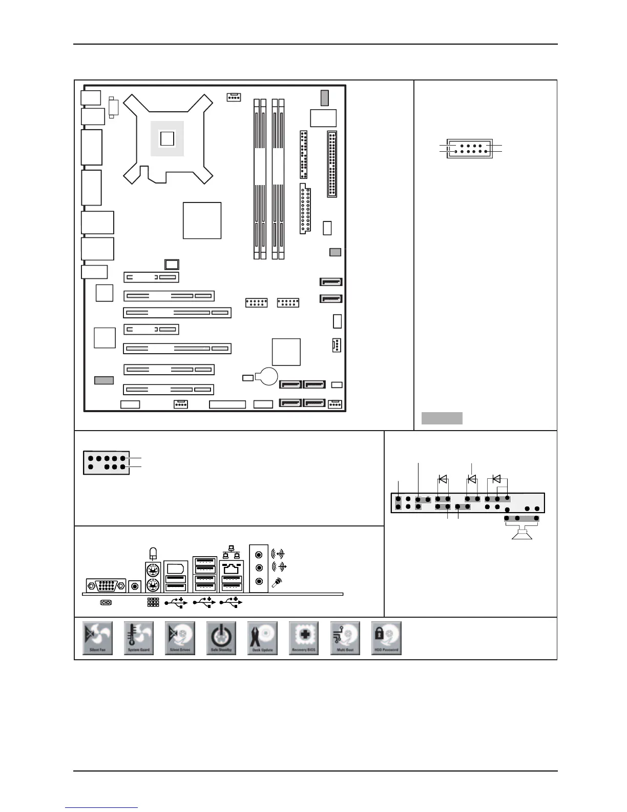
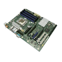
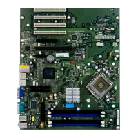
Mainboard D2608 - Internal connecto
rs and slots
External connectors rear
USB – dual channel
1
2
11
12
1 = Key
(internal or external via
special wire)
3 = VCC X
5 = Data negative Port X
4 = VCC Y
2 = Not connected
7 = Data positive Port X
9 = GND X
11 = Key
10 = GND Y
6 = Data negative Port Y
12 = Not connected
optional
8 = Data positive Port Y
Front panel
1) Both connector positions possible
1 =
2 =
3 =
4 =
Micro input left
Analog GND
Micro input right
Presence Detect
High Definition Audio
5 =
6 =
7 =
8 =
9 =
10 =
Right line / Headphone output
Sense 1 input
Jack sense Send
Key
Left line / Headphone output
Sense 2 return
2) 2pin or 3pin connector possible
1
2
HD-LED
Power On/Off
Recovery Password
1)
Message LED
Reset
Power On LED
2)
Speaker
Recovery inserted = The system starts
from floppy and allows a BIOS recovery
Password inserted = System- and BIOS
Password are skipped when device is
switched on
A26361-D2608-Z240-1-8N19
1
2
Fir
SPDIF
ewire
Battery
TPM
Enable
Fan Control
SCSI-LED-
Connector
Audio
Frontpanel
Power supply
SATA2
SATA3
Intrusion
Floppy Connector
Front Panel
USB
Port 4+5
USB
Port 8+9
LCD-
Connector
Fan 3
Fan 2
Para.Port
Firewire
intern
Fan 4
Fan 1
SATA4
SATA5
SATA0
SATA1
Power supply 1
PCIe16
PCIe16
PCI2
PCI3
PCIe1
PCIe4
MCH
CPU
LGA775
ICH9DO
Super
I/O
PCI1
1394
LAN
S/PDIF
OUT
COM1
COM2
SPDIF
PS2
FW
USB
6+7
USB
1+3
10+11
LAN
USB
0+2
Audio
LAN
Note:
Power supplies with 4-pin or
8-pin connector (+12V
processor power) can be used.
24
Channel A
Channel B
13
A26361-D2608-Z211-1-8N19, edition 1