Forecast of Cause:
1. Indoor unit Controller PCB failure
2. Wireless LAN adapter PCB failure
3. Wiring connection failure
Wireless LAN adapter Non-Energized
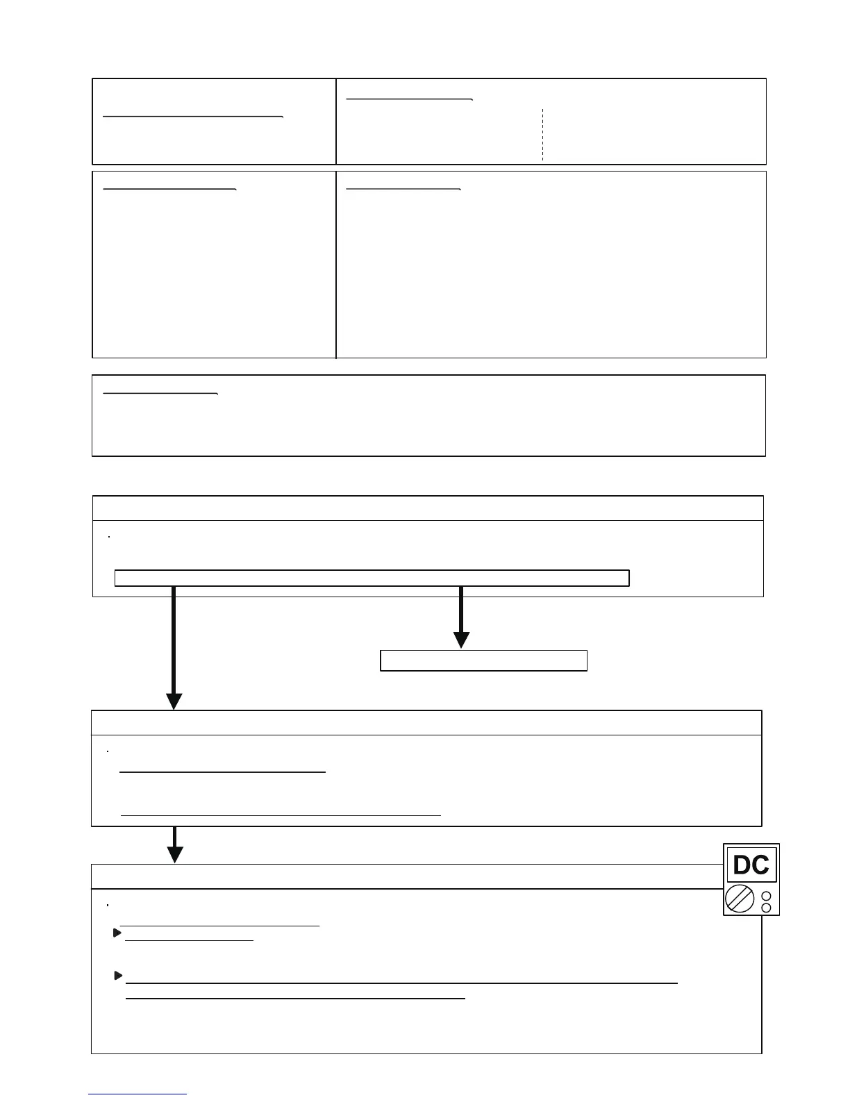
Trouble shooting 101
INDOOR UNIT Error Method:
Detective Actuators: Detective details:
Indicate of Display:
Indoor Unit :
Operation lamp: 1 time Flash
Timer lamp : 8 time Flash
ERROR CODE : [ 18 ]
Wireless LAN adapter :
LED 1 (Green) : OFF
LED 2 (Orange) : OFF
Indoor unit Controller PCB
Wireless LAN adapter PCB
When the does not output the DC12 voltage from Controller PCB.
NO
Check Point 1 : Cheak the Sleep mode
Press the Wireless LAN adapter setting button the 3 seconds or more.
OK
Check Point 2 : Cheak the connection
Check any loose or removed connection of between the Wireless LAN adapter PCB and Controller PCB
>If there is abnormal condition, correct it.
Check the connection condition on the Controller PCB
>If there is loose connector, open cable or miswiring, correct it.
Check Point 3 : Cheak the Wireless LAN adapter PCB and Controller PCB
Check Voltage at CN12 (terminal 1-2) of Controller PCB.
>If it is DC 0V, Controller PCB is failure.
Replace Controller PCB.
>If it is DC12V, Wireless LAN adapter PCB failure.
Replace Wireless LAN adapter and please cancel the air conditioner of the registration on the Mobile App.
After the replace adapter, Please perform the pairing on the App.
Wireless LAN adapter : LED 1 (Green) : Flashing Fast , LED 2 (Orange) : Flashing Fast
Did the display pattern will change?
YES
Refer To “Trouble shooting 98 ”
>> Refer to “ Air conditioning unregistration method”
>> Refer to “ Air conditioner registration Paring Method”
04-110
 Loading...