PROTECTIVE :VINYL
This adhesive vinyl (included inside the packing) protects the instruments against
water drippings, as in commercial refrigerators, for example. Do the application after
finishing the electrical connections.
Remove the protective paper
and apply the vinyl on the entire
superior part of the device,
folding the flaps as indicated by
the arrows.
72 mm
Dimension of the clipping
for setting of the instrument
in panel
29 mm
®
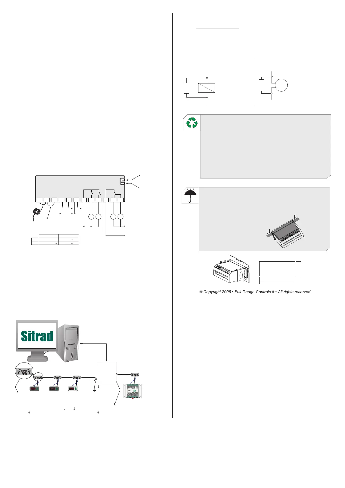
12 - INTEGRATING CONTROLLERS, RS-485 SERIAL INTERFACE AND
COMPUTER
11 - WIRING DIAGRAM
ENVIRONMENTAL INFORMATION
Package:
The packages material are 100% recyclable. Just dispose it through specialized
recyclers.
Products:
The electro components of Full Gauge controllers can be recycled or reused if it is
disassembled for specialized companies.
Disposal:
Do not burn or throw in domestic garbage the controllers which have reached the end-of-
life. Observe the respectively law in your region concerning the environmental
responsible manner of dispose its devices. In case of any doubts, contact Full Gauge
controls for assistance.
10.3 - Data recording in the event of a power outage
With the battery connected, as described in item 10.1 and the datalogger activated, the
MT-543Ri LOG will record the temperature in the internal memory even in the event of a
power outage. These records can be configured to be recorded at preset time intervals (F37)
and/or with the temperature variation (F38). If the temperature variation data record is disabled,
the device will read the temperature sensor only at the set time intervals, therefore using less
energy. With the temperature change recording activated, the sensor will be constantly read,
using more energy, but recording all the details of the temperature variation.
10.4 - Battery Precautions
- Avoid unnecessarily draining the battery;
- If the appliance is not in use, the battery should be disconnected;
- If a greater time interval between each sample is set, the datalogger will use less battery power;
- If not required, disable the F38 function to avoid wasting the energy used in reading the
temperature sensor.
OUT 1
OUT 2
C2
C1
COMMON OUT 1 AND 2
OUT 3 NO
OUT 3 NC
C3B
C3A
Loads
supply
C3A and C3B
S1
(black)
Sensor
4
5
6
7
8
9
10
11
12
321 21
Serial communication
RS-485
Digital input
A B
COMMON OUT 3
Loads
supply
C1 and C2
Power
supply
IMPORTANT
According to the chapters of norm IEC 60364:
1: Install protector against overvoltage on the power supply
2: Sensor cables and signal cables of the computer may be joined, but not in the same electric conduit
through which the electric input and the activation of the loads run
3: Install transient suppresors (RC filters) parallel to the loads as to increase the product life of the
relays.
Schematic for the connection of supresors
to contactors
Suppresor
A1
A2
A1 and A2 are the
contactor coil terminals.
Schematic for the connection of supresors to
direct activation loads
Load
Suppresor
For direct activation the maximum
specified current should be taken
into consideration.
A B
RS-485 Network
RS-485 Serial Interface
®
Device used to establish the
connection Full Gauge Controls’
instruments with the Sitrad .
Instrument
RS-485 Network
External
mesh
A
B
A
A
B B
A
B
A
A
B B
A
B
A
A
B B
A
B
A
B
A
B
A
A
B B
A
B
Serial interface
RS-485
Full Gauge
MOD 64
A
A
B B
A
B
terminal
grounded
Distribution Box
Used to connect more than one instrument to the Interface. The wire's connections must
be made in agreement with the following rules: terminal A of the instrument connects to
the terminal A of the distribution box, that must be connected with the terminal A of the
Interface. Repeat the action for terminals B and , being the cable shield.
The terminal of distribution box must be connected to the respective terminals of
each instrument.
Battery
connection (*)
Above specified current use
a contactor.
Note 1: Sensor cable length can be increased by the user until 200 meters, using 2 x 24 AWG cable. For
immersion in water use thermometric well.
(*) The MT-543Ri LOG comes with an internal battery disconnected for storage. Before installing
the instrument, connect it to the terminals 2 and 3 through a wire, as shown.
Note 2: After connecting the terminals as indicated, keep the instrument powered on for at least
ten hours for battery charging.
4 - 5
4 - 6
12V
24V
MT-543Ri LOG
-
90 ~ 264V
MT-543RiL LOG
0
(12V ) (24V )
90 ~ 264V
10 - INTERNAL BATTERY
10.1 - Battery connection
The MT-543Ri LOG has an internal rechargeable battery. This battery provides the power to
operate the clock and record the data in the memory in the event of a power outage. The device leaves
the factory with the battery disconnected for storage. Before installing the instrument, the battery must
be connected using terminals 2 and 3, using a wire as shown in the wiring diagram.
10.2 - Clock
The MT-543Ri LOG has an internal clock to record data in its memory. To continue operation,
even in the event of a power outage, the battery must be connected as described in item 10.1. If the
battery is disconnected or discharged, when energizing the device, the following message will appear
indicating that the date and time should be set.
PUMP
AUX
1
AUX 2
MICROSOL II plus
OUT
1
OUT 2
OUT 3
PCT-400R plus
OUT 4
ALMR
 Loading...