EasyManua.ls Logo

Full Gauge Controls Evolution TC-900E Power - User Manual

Full Gauge Controls Evolution TC-900E Power
5 pages
Print Icon
To Next Page IconTo Next Page
Loading...
4. INDICATIONS AND KEYS
5.1 INSTALLATION - ELECTRICAL CONNECTIONS
6. OPERATIONS
6.1 Quick Access Menu Map
To access or navigate the quick access menu using the ;(short press) key while the controller is
displaying the temperature. For every touch, the next function in the list is displayed. To confirm, use the
/(short press) key.
6.2 Quick access keys map
When the controller is on temperature display, the following keys serve as a shortcut for the following
functions:
1. DESCRIPTION
2. APPLICATION
3. TECHNICAL SPECIFICATIONS
For frozen products, it automates the defrost processes according to the need of installation (smart
defrost). The ambient temperature control has a normal setpoint and an economic setpoint, apart from
the fast freezing function and alarm functions indicating open door. Its output relay directly controls
compressors of up to 1HP and its defrost output has a current capacity of 10A.
It also features a digital filter, intended to simulate a mass increase in the ambient sensor (S1), thus
increasing its response time (thermal inertia) and avoiding unnecessary drives of the compressor. It also
includes a smart key, lock system and a control functions shutdown mode.
To drive inductive loads (motors and pumps) of up to 2HP, use the eTC-900 2HP.
Product complies with UL Inc. (United States and Canada) and .
Cold Storage Rooms
Display freezers
NSF (United States)
evolution
Connection 115 Vac
/
<
<
<
<
Pressed for 2 seconds: setpoint adjustment.
Short press: displays process.
Short press: display of minimum and maximum measurement records.
Enters the functions selection.
6.3 Basic operations
6.3.1Setting the desired temperature
To access the setpoints setup menu press / for 2 seconds. The message [SP,,] will appear on the
display followed by the normal setpoint set value. Use the > or< to modify the value and confirm by
pressing /. Immediately, the message [SP-e] appears indicating the setting of the economic
setpoint. Again, use the > or < keys to modify the value and confirm by pressing /. Finally, the
[----] indication signals the setup completion. The setpoints can also be adjusted individually in the
quick access menu.
<
Pressed for 2 seconds: inhibits audible alarm.
<
Pressed for 2 seconds: when displaying records, it cleans the history.
1
5
6
7
8
2
3
4
9 10
11 12
13
14
15 16
17
Sensor S1
D1/S3
D2
Sensor S2
230 Vac
COMP
DEFR
FANS /
Panel (Front View)
Panel
(Side View)
Dimension of the clipping
for fixing of the
instrument in panel
71 mm± 0,5
29 mm± 0,5
DEFR 2
;
Enters the quick access menu.
1
5
6
7
8
2
3
4
9 10
11 12
13
14
15 16
17
Sensor S1
D1/S3
D2
Sensor S2
COMP
DEFR
Connection 230 Vac
115 Vac
FANS /
DEFR 2
5. INSTALLATION - ASSEMBLING
and
Control functions
shutdown
Functions
lockdown
Serial
programming
Protection
level
IP 65
FRONT
Fast Freezing
FAST FREEZING (ON/OFF)
;
TC-900e POWER
;
ECONOMIC SETPOINT(ON/OFF)
TC-900e POWER
;
DEFROST (ON/OFF)
TC-900e POWER
;
FUNCTIONS LOCKDOWN
TC-900e POWER
;
CONTROL FUNCTIONS
(ON/OFF)
TC-900e POWER
NORMAL SETPOINT
;
TC-900e POWER
ECONOMIC SETPOINT
;
TC-900e POWER
MIN. AND MAX. TEMPERATURE
RECORD
;
TC-900e POWER
ERASE MIN. AND MAX.
VALUES
;
TC-900e POWER
EXIT FUNCTION
;
TC-900e POWER
FUNCTION SELECTION
;
TC-900e POWER
The sensor S1 (black)
must be in the ambient.
The sensor S2 (gray) must
be placed in the evaporator
through metallic cramp.
DIGITAL CONTROLLER FOR
REFRIGERATION AND DEFROST
Ver
.07
TC-900e POWER
<
ATTENTION
FOR INSTALLATIONS WHERE A SEALING IS REQUIRED TO
AVOID LIQUID CONTACT, THE CUT FOR THE CONTROLLER
MUST BE OF 70,5X29mm MAXIMUM. THE SIDE LOCKS MUST
BE FIXED SO IT PRESSES THE RUBBER SEALING AVOIDING
INFILTRATION BETWEEN THE CUT AND THE CONTROLLER.
IMPORTANT
SCREWDRIVER SLOT 3/32''(2.4mm) FOR ADJUSTMENTS IN THE
SIGNAL TERMINALS;
SCREWDRIVER PHILLIPS #1 FOR ADJUSTMENTS IN THE POWER
TERMINALS;
THE USE OF APPROPRIATE TOOLS IS ESSENTIAL TO AVOID DAMAGE
IN THE CONNECTION AT INSTRUMENT TERMINALS:
Pressed for 4 seconds: performs manual defrost.
TC-900e
POWER
TC-900e
POWER
TC-900e POWER
Set key
Quick Access
Menu Key
Increase key
Decrease key
Compressor output
indication LED
Fan indication LED
Defrost indication LED
Functions lock indication LED
Control functions shutdown
indication LED
Temperature unit indication LED
Control temperature
-50°C to 105°C / -58°F to 221°F
Power supply
TC-900E POWER: 115 or 230Vac ±10% (50/60Hz)
TC-900EL POWER: 12 or 24Vac/dc +10%
Operating temperature
0 to 50°C / 32 to 122°F
Operating humidity
10 to 85 %RH (without condensation)
Dimensions (mm)
76 x 34 x 77 mm (WxHxD)
Load current (outputs)
COMP: 12(8)A / 240Vac 1HP
DEFR: 10A / 240Vac 2400W
FANS: 5(3)A / 240Vac
Dimensions of the clipping for fixing
of the instrument
71 ± 0,5 x 29 ± 0,5 mm (see item 5)
Pressed for 5 seconds: turn on/turn off the control functions.
;
TC900EPWR07-01T-15838
E251415
COMPONENT
Have this manual in the palm of
your hand by FG Finder application.
Question and Answer IconNeed help?

Do you have a question about the Full Gauge Controls Evolution TC-900E Power and is the answer not in the manual?

Full Gauge Controls Evolution TC-900E Power Specifications

General IconGeneral
ModelTC-900E Power
Frequency50/60 Hz
DisplayLED
TypeController
OutputRelay
Operating Temperature0 to 50°C
Resolution0.1°C
Control OutputRelay
Storage Temperature-20 to 60°C

Summary

Product Description and Application

Product Description

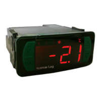
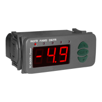
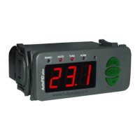
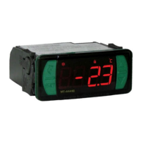
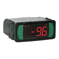
Overview of the TC-900E POWER digital controller for refrigeration and defrost processes.

Application Areas

Identifies suitable environments for the controller, such as cold storage rooms and display freezers.

Technical Specifications

Controller Interface and Installation

Indications and Keys Overview

Description of controller indicators (LEDs) and operational keys like SET, Increase, Decrease, and Quick Access Menu.

Installation and Assembling

Guidelines for physically installing the controller, including panel cutout and mounting considerations.

Electrical Connections

Wiring diagrams and terminal connections for 115 Vac and 230 Vac power supplies.

Controller Operations and Functions

Quick Access Menu and Key Functions

Navigating and using the quick access menu and associated keys for various controller functions.

Fast Freezing Operation

Enabling and disabling the fast freezing mode to accelerate the cooling process.

Economic Setpoint (SPE) Utilization

Utilizing the economic setpoint for energy savings with flexible temperature control parameters.

Manual Defrost Procedure

Initiating and deactivating the defrost process manually via the quick access menu or external switch.

Determining Defrost End by Temperature

Procedure to correctly set the defrost end temperature based on observed evaporator ice melting.

Dual Evaporator Defrost Management

Configuration for managing defrost cycles when using two evaporators simultaneously.

Functions Lockdown and Shutdown

Securing the controller by locking functions and disabling control operations.

Process Stage and Sensor Monitoring

Monitoring the controller's current process stage, elapsed time, and temperature readings from sensors.

Temperature Record Viewing and Clearing

Viewing and clearing the recorded minimum and maximum temperatures for each sensor.

Temperature Unit Selection

Changing the temperature display unit between Celsius and Fahrenheit.

Advanced Operation and Parameter Access

Accessing and modifying advanced controller parameters using an access code.

Parameter Descriptions and Tables

Parameter Table

A comprehensive table detailing available parameters, their descriptions, and value ranges in Celsius and Fahrenheit.

Parameter Descriptions (F01-F06)

Detailed explanations for parameters F01 (Access Code) through F06 (Delay at start).

Parameter Descriptions (F07-F13)

Detailed explanations for parameters F07 (High ambient temp alarm) through F13 (Evaporator temp end defrost).

Parameter Descriptions (F14-F20)

Detailed explanations for parameters F14 (Max defrost time) through F20 (Max fan return time).

Parameter Descriptions (F21-F28)

Detailed explanations for parameters F21 (Fan operating mode) through F28 (Control differential economic).

Parameter Descriptions (F29-F38)

Detailed explanations for parameters F29 (Closed door economy) through F38 (Compressor off time S1 failure).

Parameter Descriptions (F39-F46)

Detailed explanations for parameters F39 (Defrost start condition) through F46 (Compressor on time without setpoint).

Parameter Descriptions (F47-F51)

Detailed explanations for parameters F47 (Low ambient temp alarm) through F51 (Buzzer enabling).

Parameter Descriptions (F52-F58)

Detailed explanations for parameters F52 (Digital input 1/Sensor S3) through F58 (Time for functions lock).

Signals, Optional Items, and Warranty

Error and Status Signals

List and explanation of error codes (Err1, Err2, Err3) and operational status signals (ECO, OP, etc.).

Optional Accessories Overview

Information on optional items like EasyProg, Ecase, and Extension Frame for enhanced functionality.

Warranty and Disclaimer Information

Details on the product warranty, exceptions, and procedures for claiming warranty service.

Related product manuals