PSYCHROMETRIC CONTROLLER
OF AIR RELATIVE HUMIDITY
AND TEMPERATURE
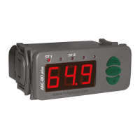
AHC-80 plus
Ver.01
1. DESCRIPTION
The AHC-80 plus is a psychrometric controller that has two totally configurable stages. It is designed
to control the relative humidity of the air and temperature for the: acclimatization of stocking of fruits and
flowers, air conditioning, textile industry, laboratories, operating rooms, concrete durability trials, wood
drying, among other applications.
The measurement is made using the temperature difference between a dry bulb and a wet bulb. It is a
psychrometric, acknowledged as a precise and stable method for determining the relative humidity of
the air.
This controller is very user friendly, and offers the user a great deal of ease in adjusting the configuration
parameters.
2. TECHNICAL SPECIFICATION
- Power supply: 115/230Vac (50/60Hz)
- Control temperature: -5.0 to 50.0°C (±0.1°C)
- Control humidity: 40 to 100%RH (±1%RH)
- Operating temperature: 0 to 50 ºC
- Operating humidity: 10 to 90%RH (without condensation)
- Maximum current per output: 8(3) A / 250Vac 1/4HP
- Dimensions: 71 x 28 x 71mm
3. CONFIGURATION
3.1 - Temperature and huimidity control (SETPOINTS)
- Press for two seconds until the following figure appears .
- If the function has a value of 0 or 1 will appear as well as with the values of the
adjusted temperature and humidity.
- If the function has a value of 2 or 3 will appear as well as with the value of the
adjusted humidity.
- Use the keys and to modify the values, and when ready, press to confirm.
3.2 - Parameters alteration (advanced functions)
- Acess the advanced functions by pressing simultaneously the keys and for 2 seconds until
appears , releasing after that. Soon appears , so press (short touch).
- Use the keys and to enter the acess code (123), when ready press .
- Use the keys and to acess the desired function.
- After select the function, press (short touch) to visualize the value configured for that function.
- Use the keys and to change the value and, when ready, press to save the configured value
and return to functions menu.
- To return the normal operation, press (long touch) until appears.
SET
SET
SET
SET
SET
SET
SET
Description
Minimum
Maximum
Unit
Access code (123)
Atmospheric pressure
Operating mode for the 1st stage
Minimum setpoint allowed for the 1st stage
Maximum setpoint allowed for the 1st stage
Control differential (hysteresis) for the 1st stage
Delay for restart of the output for the 1st stage
Operating mode for the 2nd stage
Minimum setpoint allowed for the 2nd stage
Maximum setpoint allowed for the 2nd stage
Control differential (hysteresis) for the 2nd stage
Delay for restart of the output for the 2nd stage
Cyclical timer for the 2nd stage - time on
Cyclical timer for the 2nd stage - time off
Preferential indication
Address of the instrument on the network RS-485
-
mmHg
-
°C (%RH)
°C (%RH)
°C (%RH)
sec.
-
%RH
%RH
%RH
sec.
sec.
sec.
-
-
-99
400
(*)
-5.0 (1.0)
-5.0 (1.0)
0.1 (1.0)
0
(**)
1.0
1.0
1.0
0
0
0
(***)
001
999
800
(*)
50.0 (100)
50.0 (100)
20.0
999
(**)
100
100
20.0
999
999
999
(***)
247
3.3 - Advanced functions
Fun
(**) Operating mode for the 2nd stage
Dehumidification
Humidification
(***)Preferential indication
Temperature / humidity
Only temperature
Only humidity
(*) Operating mode for the 1st stage
Refrigeration
Heating
Dehumidification
Humidification
4. STANDARDIZATION (LOCAL CALIBRATION)
Recommended execution when:
- the probe is substituted;
- the length of the sensor cable is altered.
In these cases, small deviations may arise when measuring temperatures, which may be compensated.
For this purpose, proceed in the following manner:
- Place the probe fully into a bucket of water that is a temperature similar to that of the chamber;
- Keep this water moving, and monitor the temperature using a good quality thermometer (reference).
- Wait a few minutes for the temperatures of the dry bulb and the wet bulb to stabilize and equalize to the
temperature indicated by the reference thermometer, pursuant to what is described below:
- Simultaneously press and for ten seconds until appears.
-Releasing the keys, the temperature will appear to be adjusted, according to the reference
thermometer.
- Use the keys and to adjust the value an, when ready, press to memorize the new value.
REMARKS 1 The length of the sensors cable may be increased by the user itself, using a PP 2x24 AWG
cable, additionally supplied by Full Gauge Controls upon request.
Substitute the cordon that covers the humid bulb by another one double cordon made of white cotton,
when necessary.
REMARKS 2: In order to obtain a reliable humidity indication, wait at least 20 minutes for the
temperatures to stabilize, then reinstall the probe.
5. VISUALIZATION OF THE TEMPERATURE OF THE WET BULB
To visualize the temperature of the wet bulb, all you have to do is touch the key .
The message will appear, and then the temperature measured by the wet bulb.
SET
SET
6. MAXIMUM AND MINIMUM LOGS
Press . The display will indicate followed by the maximum and minimum temperatures
registered. Then the will appear, followed by the minimum and maximum humidity levels
registered.
Note: To restart the records you just have to keep the key pressed during the viewing of the
minimum and maximum temperatures until is displayed.
7. VISUALIZATION OF THE OTHER VARIABLE
If the function is configured to only visualize the temperature or only visualize the humidity, you
may visualize the other variable through a simple touch of the key .
8. INSTALLATION OF THE PROBE FOR THE AHC-80 plus
1. Attach the stainless steel reservoir through the 2 holes. (fig. 01)
2. Fill the plastic recipient with water. (fig. 02)
3. Place the plastic recipient in the stainless steel
reservoir, as indicated in the figure.(fig. 03)
(fig. 01) (fig. 02) (fig. 03)
4. Leave the silicon hose (disconnected from the probe) with it pointing down, let the water run until you
notice bubbles of air rising in the plastic recipient. This process will guarantee that there is no air inside
the hose.
5. Slowly lift the end of the silicon hose (fig. 04), using the upper level of the water in the hose to
determine the level inside the reservoir. Using chalk, mark this level on the wall..
6. Use the mark made on the wall to position the probe (fig. 05) so that the stainless steel part (fig. 06) of
the probe has its middle positioned to the center of the mark. Guaranteeing that through communication
vessels, there is water up to half of the stainless steel part, and so we have the humid covering in the
liquid.
7.Connect the silicon hose to the probe. Take care that the covering is in contact with the water, and that
there is plenty of water in the plastic recipient.
(fig. 04)
(fig. 05) (fig. 06)
9. MESSAGES AND SIGNS
Sensor for the dry bulb is disconnected or is not in operating range
Sensor for the wet bulb is disconnected or is not in operating range
Excessive difference in temperature between the dry and wet bulbs
Temperature of the wet bulb is higher than the dry bulb
Atmospheric pressure (in mmHg):
The formula for calculating the atmospheric pressure based on the altitude is:
P (mmHg) 0,00000446171 x - 0,091019 x + 759,787
2
@
where x = altitude (in meters)
ST1
AHC-80 plus
ST2
Obs: The tube can not suffer
alterations in the cut.
AHC80PL1-09T-10842