Do you have a question about the Full Gauge Controls RCK-862 plus and is the answer not in the manual?
Steps for mounting the controller on a DIN rail for secure installation.
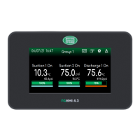
Displays the basic status of suction and discharge lines within a group.
Provides a view of the basic suction status, including setpoint and pressure.
Displays the basic status of the enabled discharge line.
Shows outputs connected, their status, and capacity control status.
Displays individual pressure switch screens accessed from the Control Menu.
Displays individual thermostat screens accessed from the Control Menu.
Allows viewing the status of all inputs and outputs and checking their function.
Thermostat information accessed from the Control Menu.
Allows viewing the status of outputs of rotation output sets.
Sets suction control parameters via menu.
Controls compressor capacity using ON/OFF modulation.
Controls VCC using analog or digital outputs.
Explains different suction control modes like Linear, Rotation, Dead Zone.
Activates/shuts down compressors sequentially at equal pressure intervals.
Linear mode for ON/OFF compressors with unloaders using digital outputs.
Linear mode with VCC and ON/OFF compressors.
Linear mode for VCC-Analog compressors using 0-10V signal.
Linear mode for VCC-Digital compressors with PWM solenoid valves.
Operates compressors based on operating hours for rotation.
Creates a control region around setpoint without immediate start/stop.
Combines Dead Zone mode with rotation for compressor start/stop preference.
Optimizes compressor use based on capacity for thermal demand.
Improves system stability by combining proportional and integral control.
Defines fan actuation and shutdown preferences for discharge control.
Control based on monitoring pressure or temperature variables.
Controls fan actuation/shutdown sequentially with pressure/temperature intervals.
Linear mode for ON/OFF fans using digital outputs.
Controls fans using an analog output (0-10V) as an inverter.
Linear mode with inverter fan and ON/OFF fans.
Operates fans based on hourly rotation of work hours.
Creates a control region around setpoint for fans.
Combines Dead Zone mode with rotation for fan start/stop preference.
Improves system stability by combining proportional and integral control for fans.
Collects refrigerant by turning off cooling groups.
Protects compressors with thermostats measuring temperature.
Reduces discharge pressure by controlling external air temperature.
Controls adiabatic condensation using temperature sensors.
Controls adiabatic condensation using dry and wet bulb sensors.
Controls adiabatic condensation using a single dry bulb temperature sensor.
Controls adiabatic condensation using differential and temperature limits.
Cycles adiabatic condensation output on/off using timer parameters.
Lowers discharge pressure and energy consumption based on air temperature.
Configures up to 3 individual pressure switches independently from main control.
Configures up to 6 individual thermostats for heating or cooling.
Configures up to 3 sets of outputs with rotation for pumps.
Configures a digital output to indicate controller operation status.
Displays active alarms, alarms on reset, and alarm history.
Configures automatic resets for protection alarms.
Configures digital outputs for alarm signaling with visual alarm.
Lists system alarms with description and effect.
Details system alarms like clock not set or manual reset.
Lists alarms related to suction pressure switches.
Lists alarms related to discharge pressure switches.
Lists alarms for individual pressure switches.
Lists alarms for individual thermostats.
Lists alarms for rotating output sets.
Lists alarms for communication failures with expansions.
Configures system units, language, buzzer, and display.
Configures RS-485 communication ports for Sitrad and MODBUS.
Details network structure for Sitrad Pro software communication.
Specifies MODBUS-RTU protocol compatibility and commands.
Explains expanding inputs/outputs using expansion modules.
Manages recipes and updates controller firmware via USB.
Copies controller recipes to a pen drive.
Copies recipes from a pen drive to the controller.
Updates the controller firmware using a file on a USB drive.
Restores all parameters to factory default settings.
Settings related to groups of suction/discharge lines.
Controller waits before enabling pressure switches after activation.
Defines the amount of suction pressure switches controlled.
Defines the amount of discharge pressure switches controlled.
Links suction pressure switches with control groups.
Defines the refrigerant used in the group.
Defines time for economy setpoint change to economy mode.
Defines time for economy setpoint change to normal mode.
Parameters for suction pressure switch control (x=1, 2, or 3).
Configures the type of compressor actuation (On/Off, VCC-Analog, VCC-Digital).
Determines preferred actuation of compressor outputs using auxiliary digital outputs.
Defines the sequence for compressor and unloader actuation.
Defines the sequence for compressor and unloader shutdown.
Analog output address for compressor 01 (VCC-Analog).
Digital output address for compressor main output.
Digital output address for compressor auxiliary output 01.
Digital output address for compressor auxiliary output 02.
Digital output address for compressor auxiliary output 03.
Minimum time between two actuations of main compressor digital outputs.
Minimum time between two shutdowns of main compressor digital outputs.
Minimum time a compressor remains on.
Minimum time a compressor remains off.
Time between actuation of two auxiliary unloader outputs.
Time between shutdown of two auxiliary unloader outputs.
Time the Variable Capacity Compressor remains in the starting condition.
Validates need to actuate/shutdown compression stage to avoid unnecessary actions.
Sets minimum capacity value for digital variable capacity compressor.
Configures fixed modulation signal period for Digital Variable Capacity Compressor.
Sets minimum time valves of VCC-Digital compressors remain on or off.
Maximum time compressor operates at minimum capacity or with auxiliary outputs on.
Parameters for discharge pressure switch control (x=1, 2, or 3).
Determines discharge control by pressure or temperature.
Pressure value for controlling discharge, shutting off all fans.
Alternative pressure setpoint, usually less than normal setpoint.
Pressure range for controlling fans linked with digital outputs.
Pressure range for controlling fan linked with analog output.
Pressure differential below setpoint allowing compressors to shut off.
Pressure differential above setpoint allowing compressors to be actuated.
Lowest possible value for setpoint adjustment to prevent unreasonably low pressures.
Highest possible value for setpoint adjustment to prevent unreasonably high pressures.
Temperature value for controlling discharge, shutting off all fans.
Alternative temperature setpoint, usually lower than normal setpoint.
Temperature range for controlling fans linked with digital outputs.
Temperature range for controlling fan linked with analog output.
Lower limit to avoid regulating excessively low temperatures by mistake.
Upper limit to avoid regulating excessively high temperatures by mistake.
Lowest possible value for setpoint adjustment to avoid excessively low temperatures.
Highest possible value for setpoint adjustment to avoid excessively high temperatures.
Specifies the pressure sensor used to control the discharge.
Specifies backup pressure sensor for discharge control.
Discharge temperature sensor address (refrigerant).
Specifies backup temperature sensor for discharge control.
Specifies the dry air bulb temperature sensor.
Number of fans used to control the discharge.
Selects Fan 1 modulation type: ON/OFF or INVERTER.
Analog output address for fan 1 inverter.
Digital output address of fans 1 to 6.
Minimum time between two actuations of main fan digital outputs.
Minimum time between two shutdowns of main fan digital outputs.
Minimum time a fan will remain on.
Minimum time a fan will remain off.
Time analog output remains at starting value.
Validates need to actuate/shutdown fan stage to avoid unnecessary actions.
Enables Proportional/Integral (PI) control for fans.
Parameters related to alarm settings.
Configures time to validate and inhibit alarms.
Time between alarm condition identified and its indication.
Time alarm events are considered after controller is energized.
Alarms assigned separately for each suction pressure switch.
Configures suction alarms (low/high pressure, overheating, etc.).
Enables alarm when pressure is lower than configured value.
Enables alarm when pressure is higher than configured value.
Pressure difference to exit alarm situation.
Enables alarm when temperature is lower than configured value.
Enables alarm when temperature is lower than configured value.
Enables alarm when overheating is higher than configured value.
Digital output address for alarm.
Configures compressor/fan status in case of sensor fault.
Defines compressor status (Off, On, Cyclic) in case of sensor fault.
Time compressor or fan remains on in cycle timer mode.
Time compressor or fan remains off in cycle timer mode.
Allows configuring up to 8 auxiliary inputs with specific functions.
Configures input address, function, and contact type.
Links input x with pressure switch, group, or auxiliary function.
Defines input function based on actuation/shutdown.
Details auxiliary features like Pump Down and Adiabatic Condensation.
Configures Pump Down function parameters.
Configures output control and shutdown temperatures for compressor thermostats.
Configures control mode, temperatures, and differentials for adiabatic condensation.
Temperature of dry bulb sensor to actuate output.
Temperature of external sensor for shutting down output.
Value of difference between dry/wet bulb temps for actuating output.
Value of difference between dry/wet bulb temps for shutting down output.
Minimum ambient temperature for adiabatic condensation differential control.
Maximum time to reach shutdown differential.
Time control waits for new attempt to reach shutdown differential.
Specifies the wet bulb temperature sensor.
Digital output address for adiabatic condensation.
Temperature value for starting discharge setpoint control.
Minimum pressure setpoint value for the discharge.
Minimum subcooling value. Setpoint reduction stops at this point.
Logic operating start time for floating condensation.
Logic operating end time for floating condensation.
Configures individual pressure switches (operation mode, setpoints, hysteresis).
Configures the operation mode for individual pressure switches.
Output pressure setpoints for individual pressure switches.
Hysteresis for output pressure setpoints of individual pressure switches.
Specifies the pressure sensor for individual pressure switches.
Digital output address 01-06 linked to individual pressure switch.
Enables alarm when pressure is lower than configured value.
Enables alarm when pressure is higher than configured value.
Hysteresis of pressure alarms for individual switches.
Minimum time between two actuations of main digital outputs for individual switches.
Minimum output time on/off for individual switches.
Configures individual thermostats (operation mode, setpoints, hysteresis).
Configures the operation mode for individual thermostats.
Output temperature setpoint for individual thermostats.
Temperature control hysteresis linked to individual thermostat output.
Enables alarm when temperature is lower than configured value.
Enables alarm when temperature is higher than configured value.
Hysteresis of temperature alarms for individual thermostats.
Links thermostat to a suction pressure switch.
Specifies the temperature sensor for the thermostat.
Output address linked to the individual thermostat.
Defines the actuation state of the main output.
Minimum time output on/off for thermostats.
Output address linked to defrost the individual thermostat.
Defines the operating state of the defrost output.
Time interval between defrosts.
Time interval during which thermostat remains in defrost.
Configures rotation outputs time and transition time.
Operation time of an output before entering rotation.
Time two outputs remain on during rotation.
Digital output address for rotation.
Digital output address for rotation.
Digital output that indicates controller is operating.
Time setting for maintenance of compressors and fans.
Maintenance time for compressors/fans 01 to 06.
Settings related to sensors S1 to S6.
Pressure and temperature offset configuration for sensor inputs.
Sensor pressure value at 4mA (low full scale).
Sensor pressure value at 20mA (high full scale).
Allows offsetting deviations in pressure readings.
Allows offsetting deviations in temperature readings.
Configuration of limit values for analog outputs.
Configures analog output actuation range and min/max values.
Important safety/installation notes according to NBR 5410 standard.
Details the warranty period, terms, and exceptions for Full Gauge Controls products.
| Brand | Full Gauge Controls |
|---|---|
| Model | RCK-862 plus |
| Category | Controller |
| Language | English |