EasyManua.ls Logo

Full Gauge Controls MT-514e - User Manual

Full Gauge Controls MT-514e
5 pages
Print Icon
To Next Page IconTo Next Page
Loading...
DIGITAL CONTROLLER FOR HEATING OR COOLING
WITH DEFROST AND CONFIGURABLE
ALARM OUTPUT
MT514EV01-02T-15072
4. INDICATIONS AND KEYS
5. INSTALLATION - ASSEMBLING AND ELECTRICAL CONNECTIONS
1. DESCRIPTION
2. APPLICATION
It is a temperature-based controller designed for cooling or heating applications. It is loaded with one
temperature sensor and two outputs of control, including a SPDT contact that can be used for alarm or
defrost purposes. Defrost can be electric or hot gas. The controller offers a built-in buzzer and a digital
input which can be configured for door alarm or power outage alarm, or detection of both events through
the single digital input. Two configurable preset options is available for quick parameter change. Preset
include variables such as temperature setpoint, differential and cooling time (interval between
defrosts). Other salient features include internal buzzer, IP65 frontal, min-max temperature record,
temperature sensor response-time control, tamper-proof function and control functions shutdown.
Product conforming to UL Inc. (United States and Canada) and NSF .(United States)
Vaccine refrigerators
Refrigerated counters
Freezer rooms
Hot counters
Greenhouses
evolution
MT-514 e
Ver.01
Panel (Front View)
Panel
(Side View)
Dimension of the clipping
for fixing of the
instrument in panel
71 mm± 0,5
29 mm± 0,5
FOR INSTALLATIONS WHERE A SEALING IS REQUIRED
TO AVOID LIQUID CONTACT, THE CUT FOR THE
CONTROLLER MUST BE OF 70,5X29mm MAXIMUM. THE
SIDE LOCKS MUST BE FIXED SO IT PRESSES THE
RUBBER SEALING AVOIDING INFILTRATION BETWEEN
THE CUT AND THE CONTROLLER.
ATTENTION
1
5
6
7
8
2
3
4
9
POWER
SUPPLY
SENSOR
10
11 12
13
14
15 16
17
REFR
HEAT
REFR
115 Vac
1
5
6
7
8
2
3
4
9
POWER
SUPPLY
SENSOR
10
11 12
13
14
15 16
17
230 Vac
Connection
115 Vac
Loads supply
COMMON
Connection
230 Vac
Loads supply
1
5
6
7
8
2
3
4
9
POWER
SUPPLY
SENSOR
10
11 12
13
14
15 16
17
1
5
6
7
8
2
3
4
9
POWER
SUPPLY
SENSOR
10
11 12
13
14
15 16
17
Connection
12 Vac/dc
12 Vac/dc
24 Vac/dc
Connection
24 Vac/dc
Loads supply
IMPORTANT
SCREWDRIVER SLOT 3/32''(2.4mm) FOR ADJUSTMENTS IN THE
SIGNAL TERMINALS;
SCREWDRIVER PHILLIPS #1 FOR ADJUSTMENTS IN THE POWER
TERMINALS;
WARNING
ACCESSORIES:
Only use original Full Gauge Controls accessories.
If you have any questions, please contact technical support.
AUTHORIZED SERVICE:
The installation or maintenance of the product must be performed by qualified professionals only;
THE USE OF APPROPRIATE TOOLS IS ESSENTIAL TO AVOID
DAMAGE IN THE CONNECTION AT INSTRUMENT TERMINALS:
D1
D1
Control functions
shutdown
Function
blocking
Serial
Programming
Protection
level
Defrost
IP 65
FRONT
Audible
Alarm
ALRM/
DEFR
COMMON
NO
NC
REFR
HEAT
NO
NC
COMMON
COMMON
6. OPERATIONS
6.1. Quick Access Menu Map
To access or browse in the quick access menu, use the ;key (quick touch) while the temperature is
being displayed by the controller. Each touch displays the next function of the list; for confirming, use
the/ key (quick touch). For further details, refer to chapter 6.3.
REFR
HEAT
NO
NC
REFR
HEAT
NO
NC
COMMON
COMMON
Loads supply
COMMON
COMMON
;
;
MT-514e MT-514e
;
DEFROST (ON/OFF)
;
FUNCTIONS LOCKDOWN
;
CONTROL FUNCTIONS
(ON/OFF)
ADJUSTING DESIRED
TEMPERATURE
(SETPOINT)
EXIT FUNCTION
;
FUNCTION SELECTION
;
VISUALIZATION OF
PROCESSES
;
ERASE MIN. AND MAX.
VALUES
MT-514e MT-514e
MT-514e MT-514e
MT-514e MT-514e
MIN. AND MAX.
TEMPERATURE RECORD
;
MT-514e
MT-514e
D1
D1
MT-514e
MT-514e
/
REFR
ALRM/
DEFR
/
REFR
ALRM/
DEFR
/
REFR
ALRM/
DEFR
/
(*) This instrument measures and controls temperatures of up to 200°C/392°F, using the silicone sensor cable SB59
(sold separately).
Note: The sensor cable lenght can be increased by the user up to 200 meters using PP 2 x 24 AWG cable.
3. TECHNICAL SPECIFICATIONS
Control temperature
-50 to 105ºC (-58 to 221°F)*
Power supply
MT-514 E: 115 or 230 Vac ±10%(50/60 Hz)
MT-514 EL: 12 or 24 Vac/dc +10%
Operating temperature
0 to 50 ºC / 32 to 122°F
Operating humidity
10 to 90%RH (without condensation)
Dimensions (mm)
76 x 34 x 77 mm (WxHxD)
Load current (outputs)
OUT1: 16(12)A 250Vac 2HP
OUT2: 10A / 240Vac 1/4HP
Dimensions of the clipping for fixing
of the instrument
71 ± 0,5 x 29 ± 0,5 mm (see item 5)
Set key
Quick Access
Menu Key (Flatec)
Functions lock indication LED
Temperature unit indication LED
Increase key
Decrease key
Alarm indication LED
Cooling indication LED
Heating indication LED
Defrost indication LED
DUE TO YOUR CONSTANT EVOLUTION, THE FULL GAUGE CONTROLS RESERVES THE RIGHT TO
CHANGE THE INFORMATION CONTAINED IN THIS MANUAL AT ANY TIME WITHOUT NOTICE.
BEFORE INSTALLING THE CONTROLLER, WE RECOMMEND READING THROUGH THE
ENTIRE INSTRUCTION MANUAL IN ORDER TO AVOID POSSIBLE DAMAGE TO THE
PRODUCT.
PRECAUTIONS WHEN INSTALLING THE PRODUCT:
Before performing any procedure on this instrument, disconnect it from the mains;
Ensure that the instrument has adequate ventilation and avoid installation in panels containing
devices that may cause it to operate outside the specified temperature limits;
Install the product away from sources that may generate electromagnetic disturbances such as:
motors, contactors, relays, solenoid valves, etc;
6.2 Quick access keys map
When controller is on temperature display mode, the following keys can be used as a shortcut for the
following functions:
Hold down for 2 seconds: Setpoint adjustment.
Quick touch: Current process display.
Quick touch: Maximum and minimum temperature display.
/
<
<
<
Hold down for 2 seconds: Inhibit audible alarm (buzzer).
Have this manual in the palm of
your hand by FG Finder application.
E251415
COMPONENT
Question and Answer IconNeed help?

Do you have a question about the Full Gauge Controls MT-514e and is the answer not in the manual?

Full Gauge Controls MT-514e Specifications

General IconGeneral
BrandFull Gauge Controls
ModelMT-514e
CategoryController
LanguageEnglish

Summary

Description of the MT-514 E Digital Controller

Key Features and Functionality

Details the controller's capabilities including temperature control, defrost, buzzer, digital input, and presets.

Application Areas for MT-514 E

Typical Applications

Lists common uses such as vaccine refrigerators, refrigerated counters, freezer rooms, hot counters, and greenhouses.

Technical Specifications of the MT-514 E

Power Supply and Environmental Limits

Covers power supply options, control/operating temperature ranges, operating humidity, and dimensions.

Load Current and Sensor Specifications

Details the load current for outputs and notes on sensor cable length for extended measurements.

MT-514 E Indicators and Keys Overview

Front Panel Indicators

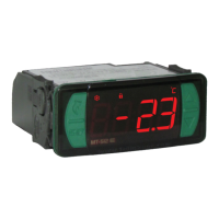
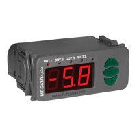
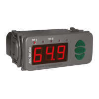
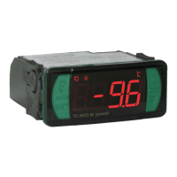
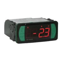
Explains the function of LEDs on the controller, including Defrost, Alarm, Heating, Cooling, and Temperature Unit.

Control Panel Keys

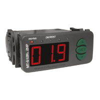
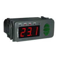
Identifies the function of the keys: Set key, Quick Access Menu Key, Increase, and Decrease.

Installation and Electrical Connections

Panel Mounting and Wiring Diagrams

Provides dimensions for panel clipping and illustrates electrical connection diagrams for various power supplies.

Operating the MT-514 E Controller

Quick Access Menu Operations

Details how to access and navigate the quick access menu for functions like Defrost, Lock, Exit, and Setpoint.

Quick Access Key Shortcuts

Explains shortcut key presses for Setpoint adjustment, current display, buzzer inhibit, and min/max temperature display.

Basic Operations of the MT-514 E

Adjusting Setpoint Temperature

Guides users on how to set the desired temperature, either directly or via presets, using the controller keys.

Manual Defrost Operation

Explains how to initiate or stop manual defrost using the quick access menu or by holding a specific key.

Functions Lockdown and Security

Describes how to enable or disable function lockdown to protect settings from unauthorized changes.

Control Functions Shutdown

Details how to turn off control functions, making the controller act only as a temperature indicator.

Visualizing Controller Processes

Explains how to view the current process status, including initial delay, cooling, heating, defrost, and shutdown states.

Minimum and Maximum Temperature Records

Guides on how to display and erase recorded minimum and maximum temperatures.

Temperature Unit Selection

Explains how to select the temperature unit (Celsius or Fahrenheit) and the implications of changing it.

Buzzer Inhibition

Describes how to temporarily inhibit the audible alarm buzzer.

Advanced Operations and Parameter Access

Accessing Advanced Parameters

Details how to access the advanced functions menu and enter the access code to modify parameters.

MT-514 E Parameters Table

Parameter Functions and Descriptions

Provides a detailed table listing all configurable parameters, their codes, ranges, units, and standard values.

Detailed Parameter Explanations

Preset Configuration (F03)

Explains how to configure the controller to use or not use presets for setpoint, differential, and cooling time.

Output 1 Operation Modes

Details parameters for Output 1 operating mode, setpoint, control differential, cooling time, and defrost time.

Setpoint Limits and Output Timings

Covers minimum/maximum setpoint limits and minimum output on/off times for Output 1.

Initial Status and Defrost Settings

Explains initial instrument status, temperature indication lock during defrost, and energization delay.

Compressor Error Handling

Details parameters for compressor status with sensor damage and time on/off during errors.

Temperature Alarms and Output 2 Modes

Covers low/high temperature alarms and various operating modes for Output 2, including defrost and alarm.

Alarm Inhibition and Digital Input

Explains alarm inhibition time, buzzer enablement, and digital input operating modes for door or power outage alarms.

Digital Input and Filter Configurations

Digital Input Connection Examples

Illustrates connection examples for digital inputs, specifically for open door or power outage detection.

Output 2 Alarm Status Timings

Details parameters for Output 2 alarm status timing when active, including permanent or timed operation.

Open Door Alarm and Digital Filter Settings

Covers open door alarm configuration, digital filter operation modes, and intensity applied to the sensor.

Functions Lockdown Time

Specifies the time in seconds for the controller to activate the functions lockdown.

Control Functions Shutdown Options

Details options for enabling/disabling control functions shutdown, even when functions are locked.

Signals and Optional Accessories

Controller Signal Indications

Lists and explains common signal indications displayed by the controller, such as errors and alarm states.

Optional Accessories

Describes optional accessories like EasyProg for parameter management and Ecase for environmental protection.

Extension Frame and Filters

Details the extension frame for installation flexibility and electrical noise suppressing filters.

Environmental and Warranty Information

Environmental Information and Disposal

Provides guidance on product packaging recyclability and proper disposal of electronic waste.

Product Warranty Terms

Outlines the two-year warranty period and conditions for manufacturing defects.

Warranty Exceptions and Loss Conditions

Lists events that void the warranty, including improper installation, misuse, or unauthorized repairs.

Warranty Claim Procedure

Explains the process for making a warranty claim, including required documentation and contact information.

Related product manuals