EasyManua.ls Logo

Full Gauge Controls TC-900R - User Manual

Full Gauge Controls TC-900R
3 pages
Print Icon
To Next Page IconTo Next Page
Loading...
DIGITAL CONTROLLER FOR
REFRIGERATION AND DEFROST
TC-900Ri power
4. CONFIGURATIONS
- Press for 2 seconds until appears , and release it after that. The adjusted operation
temperature will appear.
- Use and to change the value and then press to record it.
4.1 - Control temperature adjust (SETPOINT):
SET
SET
1. DESCRIPTION
TC-900Ri power is a control for low temperature ventilated units which automates defrosting
processes, providing great energy saving
2. APPLICATION
Counters
Refrigerating balconies
3. TECHNICAL SPECIFICATIONS
- Power supply: TC-900Ri power: 115 or 230Vac ±10%( 50/60 Hz)
TC-900RiL power: 12 or 24 Vac/dc
- Control temperature: -50 to 75° C / -58 to 167°F
- Operating temperature: 0 to 40°C / 32 to 104°F
- Operating humidity: 10 to 90% RH (without condensation)
- Resolution: 0.1°C from -10 to 75°C and 1°C outside this range /1°F in all range
- Load current (outputs): COMP: 12(8)A/240Vac 1HP (compressor, solenoid valve or contactor)
DEFR: 10A / 240Vac 1/4HP (defrost resistance or hot gas)
FANS: 5(3)A / 240Vac 1/8HP (evaporator fans)
- Dimensions: 71 x 28 x 71mm
- Sensors:
S1: ambient sensor (black cable)
S2: evaporator sensor (gray cable)
. For cooling and defrosting, works with two sensors, one
being for ambient temperatura and the other fixed to the evaporador that controls defrost ending. With
the powerful 16-amp relay, directly controls compressors up to 1 HP. The defrost output has a 10A
current capacity, as well as also having Normally Closed (NC) contact avaiable. It also has indicators in
ºC and °F and digital filters, which have the purpose of simulating an increase in mass in the
environment sensor (S1), thus increasing its response time (thermal inertia) and preventing
unnecessary activations of the compressor.
Product complies with UL Inc. (United States and Canada) and NSF (United States).
4.2 - Parameters table
DescriptionFun
Access code:123 (one hundred and twenty-three)
Control differential (hysteresis)
Offset indication for ambient sensor
Minimum setpoint allowed to the end user
Maximum setpoint allowed to the end user
Delay when the instrument is powered on
Act point of high ambient temperature alert
Refrigeration time (interval between defrosts)
Compressor delay after on (on - off)
Compressor delay after off (off - on)
Compressor status with detached ambient sensor (S1)
Defrost when the instrument is powered on
Evaporator temperature (S2) for end defrost
Maximum duration of defrost (for security)
Fan turned on during defrost
Defrost type
Min
Max
Unit
Standard
CELSIUS
FAHRENHEIT
-
0.1
-20.0
-50.0
-50.0
0
-50.0
1
0
0
0 - off
0 - no
-50.0
0=disable
0 - no
0 - electric
-
1
-36
-58
-58
0
-58
1
0
0
0 - off
0 - no
-58
0=disable
0 - no
0 - electric
-
20.0
20.0
75.0
75.0
30
75.0
999
999
999
1 - on
1 - yes
75.0
90
1 - yes
1 - hot gas
-
36
36
167
167
30
167
999
999
999
1 - on
1 - yes
167
90
1 - yes
1 - hot gas
-
º C
º C
º C
º C
min.
º C
min.
sec.
sec.
-
-
º C
min.
-
-
-
1.5
0
-50.0
75.0
0
40.0
240
0
0
1 - on
0 -no
40.0
45
0
0
-
°F
°F
°F
°F
min.
°F
min.
sec.
sec.
-
-
°F
min.
-
-
-
3
0
-58
167
0
104
240
0
0
1 - on
0 -no
104
45
0
0
Min
Max
Unit
Standard
4.3 - Parameters description
F01 - Access code (123)
To change the parameters it is necessary to use the access code.It is not necessary to use the access
code to visualize the adjusted parameters.
F02 - Control differential (hysteresis)
It is the difference of temperature (hysteresis) between to turn OFF and turn ON the refrigeration output.
Example: To control the temperature in 4.0°C with differential of 1.0°C. Soon, the refrigeration will be
turned off in 4.0°C and turned on again in 5.0°C (4.0 + 1.0)
F03 - Offset indication for ambient sensor
It allows to compensate eventual shunting lines in the reading of ambient temperature (S1) proceeding
from the exchange of the sensor or cable length alteration.
F04 - Minimum setpoint allowed to the end user
F05 - Maximum setpoint allowed to the end user
Electronic limits whose purpose is to prevent that too high or too low setpoint temperatures are
regulated.
F10 - Compressor delay after off (off-on)
It is the minimum time that compressor will keep off, it means, space of time between the last stop and
the next drive. It serves to alliviate the discharge pressure and to increase the time of useful life of the
compressor.
F11 - Compressor status with detached ambient sensor (S1)
If the ambient sensor (S1) will be damaged or outside the specified range, the compressor assumes the
configured status in this function.
Example: For counters of fruits, it is better to keep the compressor off. In counters of meat it is better to
keep the compressor on.
F12 - Defrost when the instrument is powered on
It makes possible the accomplishment of a defrost at the moment that controller is energized, for
example, in the return of electrical energy (in case of energy lack)
F13 - Evaporator temperature (S2) for end defrost
If the temperature in the evaporator (sensor S2) reaches the adjusted value, the end of defrost will be for
temperature. With this, the defrost process is optimized.
F06 - Delay when the instrument is powered on
When the instrument is powered on, its control is kept disabled during a time, delaying the start of
process. During this time, it works only as temperature indicator. It serves to prevent demand of electric
energy peaks, in case of lack or return of the same and when exists a lot of equipment connected on the
same net. For this, just adjust different times for each equipment. This delay may be of compressor or
defrost (when exist defrost on turn on).
F07 - Act point of high ambient temperature alert
If the ambient temperature (sensor S1) reaches this point during refrigeration, this will be signaled
visually through the indication blinking on display.
F08 - Refrigeration time (interval between defrosts)
It is the time which compressor will turn on and turn off only for ambient temperature and starts to be
counted when the fan is turned on , after fan-delay stage (fan return after draining).
F09 - Compressor delay after on (on-off)
It is the minimum time that compressor will keep on, it means, space of time between the last drive and
the next stop. It serves to prevent high voltage events in the electric network.
E251415
TC-900Ri
power
Ver.03
Locked temperature indication (S1) during defrost
Draining time (dripping of defrost water)
Evaporator temperature (S2) for fan return after draining
Maximum time of fan return after draining (fan-delay)
Fan on with compressor off (refrigeration)
Fan stopped for high temperature in the evaporator
Time to collect the gas before starting the defrost
Intensity of the digital filter applied to the sensor 1 (0-OFF)
Time to Key blocker
0 - no
0
-50
0
0 - no
-50
0
0
14 - no
1 - yes
30
75.0
30
1 - yes
75.0
999
9
60
-
min.
º C
min.
-
º C
sec.
-
sec.
0 - no
0
-58
0
0 - no
-58
0
0
14 - no
1 - yes
30
167
30
1 - yes
167
999
9
60
-
min.
°F
min.
-
°F
sec.
-
sec.
0 - no
10
0
1
1 - yes
75.0
0
0
14 - no
0 - no
10
0
1
1 - yes
167
0
0
14 - no
TC900RIPWV03-04T-12768
COMPONENT
Question and Answer IconNeed help?

Do you have a question about the Full Gauge Controls TC-900R and is the answer not in the manual?

Summary

Description

Application

Technical Specifications

Configurations

Control Temperature Adjust (SETPOINT)

Adjusts the control temperature by pressing buttons and confirming.

Parameters Table

Lists all configurable parameters with their min/max and default values.

Parameters Description

Provides detailed explanations for each configurable parameter (F01-F25).

Operation

Parameters Visualization

Explains how to view configured parameters and their values.

Parameters Configuration

Details the step-by-step process for changing controller parameters.

Process Stage, Elapsed Time and Evaporator Temperature

Shows how to view current process stage, time and evaporator temperature.

Manual Defrost

Instructions for initiating or stopping a manual defrost cycle.

Determine End Defrost by Temperature

Guides on setting parameters for temperature-based defrost termination.

Indicators and Alarms

Explains LED indicators and error/alarm codes for controller status.

Minimum and Maximum Temperatures Register

Details how to view and reset recorded minimum and maximum sensor temperatures.

Selection of Unit (C°; F°)

Instructions on how to switch between Celsius and Fahrenheit units.

Key Blocking

Explains how to lock/unlock the controller keys to prevent unauthorized changes.

Overview

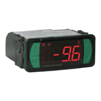
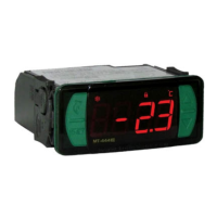
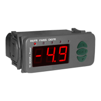
The TC-900Ri power is a sophisticated digital controller designed for low-temperature ventilated units, specifically engineered to automate defrosting processes and achieve significant energy savings. This device is adept at managing both cooling and defrosting cycles, utilizing two distinct sensors: one for ambient temperature monitoring and another fixed to the evaporator to precisely control the termination of defrost cycles. Its robust 16-amp relay enables direct control of compressors up to 1 HP, while the defrost output boasts a 10A current capacity and includes a Normally Closed (NC) contact for versatile applications. The controller features indicators for both Celsius and Fahrenheit, along with digital filters that simulate an increase in mass within the environment sensor (S1). This simulation enhances the device's response time, providing thermal inertia and preventing unnecessary activations of the compressor, thereby optimizing system efficiency and longevity. The TC-900Ri power is compliant with UL Inc. standards for the United States and Canada, as well as NSF standards for the United States, ensuring its reliability and safety in various applications such as counters and refrigerating balconies.

Usage Features:

The TC-900Ri power offers a comprehensive suite of configurable parameters and operational features to ensure precise control and efficient management of refrigeration and defrost cycles.

Control Temperature Adjustment (SETPOINT): Users can easily adjust the desired operation temperature by pressing the SET button for two seconds until "SEE" appears. Releasing the button displays the current adjusted temperature, which can then be modified using the up and down arrow keys. Pressing SET again records the new value.

Parameter Configuration: The device provides access to a detailed parameters table, allowing users to fine-tune various aspects of its operation.

  • Access Code (F01): To modify parameters, an access code (123) is required. However, visualization of adjusted parameters does not necessitate the code.
  • Control Differential (F02 - Hysteresis): This parameter defines the temperature difference between turning the refrigeration output OFF and ON. For example, if the control temperature is 4.0°C and the differential is 1.0°C, refrigeration turns off at 4.0°C and turns on again at 5.0°C (4.0 + 1.0).
  • Offset Indication for Ambient Sensor (F03): This feature compensates for potential shunting lines in the ambient temperature sensor (S1) readings, which can arise from sensor exchange or cable length alterations.
  • Setpoint Limits (F04, F05): Users can set minimum and maximum setpoint temperatures to prevent excessively high or low temperature regulations.
  • Delay When Powered On (F06): Upon power-up, the controller can be configured to delay its control functions for a specified period. This prevents electrical energy peaks, especially in environments with multiple connected devices, and can apply to both compressor and defrost starts.
  • High Ambient Temperature Alert (F07): If the ambient temperature (S1) reaches a predefined point during refrigeration, the display will visually signal this condition by blinking.
  • Refrigeration Time (F08 - Interval Between Defrosts): This parameter sets the duration for which the compressor operates based on ambient temperature. The timer starts when the fan turns on, after the fan-delay stage.
  • Compressor Delays (F09, F10):
    • After On (F09 - On-Off): Sets the minimum time the compressor remains on, preventing rapid cycling and high voltage events in the electrical network.
    • After Off (F10 - Off-On): Sets the minimum time the compressor remains off, alleviating discharge pressure and extending compressor lifespan.
  • Compressor Status with Detached Ambient Sensor (F11): In case of a damaged or out-of-range ambient sensor (S1), the compressor can be configured to either turn off (e.g., for fruit counters) or turn on (e.g., for meat counters).
  • Defrost When Powered On (F12): This allows for a defrost cycle to initiate immediately upon controller energization, useful after power outages.
  • Evaporator Temperature for End Defrost (F13): Defrost ends when the evaporator temperature (S2) reaches the adjusted value, optimizing the defrost process.
  • Maximum Duration of Defrost (F14 - Security): This sets a maximum time for defrost. If the evaporator temperature (F13) is not reached within this period, a blinking point on the display indicates that defrost ended by time, not temperature. This can occur if F13 is too high, F14 is too short, or if the sensor is detached/faulty.
  • Fan Turned On During Defrost (F15): Enables fan operation during defrost, useful for natural defrost or systems with external resistances.
  • Defrost Type (F16): Configures the defrost method as either electrical (resistances, activating the defrost output) or hot gas (activating both compressor and defrost outputs).
  • Locked Temperature Indication (S1) During Defrost (F17): Prevents visualization of ambient temperature elevation during defrost, displaying the last indication before defrost. The indication is released at the start of the refrigeration cycle after fan-delay.
  • Draining Time (F18 - Dripping of Defrost Water): Sets the necessary time for water to drip from the evaporator after defrost, during which all outputs are off. Setting this to "zero" disables this stage.
  • Evaporator Temperature for Fan Return After Draining (F19 - Fan-Delay): After draining, the refrigeration output (REFR) becomes active, but the fan only activates once the evaporator temperature (S2) falls below the adjusted value. This removes residual heat from the evaporator, preventing its transfer to the ambient.
  • Maximum Time of Fan Return After Draining (F20 - Fan-Delay): A security feature that ensures the fan-delay stage concludes within a set time if the evaporator temperature (S2) is not reached or if the sensor is detached.
  • Fan On with Compressor Off (F21): Configures fan activation during the refrigeration cycle. "0" means the fan is active only when the compressor is active, saving energy. "1" means the fan runs throughout the refrigeration cycle.
  • Fan Stopped for High Temperature in Evaporator (F22): Cycles evaporator ventilation to prevent high temperatures and pressures that could damage the compressor. If the evaporator temperature exceeds the adjusted value, the fan turns off and restarts with a fixed 2°C hysteresis.
  • Time to Collect Gas Before Defrost (F23): Collects remaining gas from the refrigeration line before defrost, enhancing system efficiency. Only the FANS output remains ON during this time.
  • Digital Filter Intensity for Sensor 1 (F24): Simulates an increase in the mass of the environment sensor (S1), increasing its response time (thermal inertia). Higher values result in longer response times, useful for applications like freezers where door openings cause rapid temperature fluctuations.
  • Time to Key Blocker (F25): Blocks key settings for security, preventing unauthorized alterations. The user can only view setpoints and settings; attempting to change them displays "LOC." To block, hold the SET key for the programmed time. To unblock, turn off and turn on the controller while holding the SET key for 10 seconds.

Process Stage, Elapsed Time, and Evaporator Temperature (S2): Pressing the up arrow key displays the current process stage, elapsed time (in minutes), and evaporator temperature (S2). If a sensor is detached or out of range, "Er2" appears.

  • DEL: Initial delay (delay to start control).
  • FAn: Fan-delay (delay to fan return).
  • rEF: Refrigeration.
  • dEF: Defrost.
  • drE: Draining.

Manual Defrost: To initiate a manual defrost, press and hold the down arrow key for 4 seconds until "DEF On" appears. To terminate an ongoing defrost, follow the same procedure until "DEF OFF" appears.

Determining End Defrost by Temperature: This feature allows users to optimize defrost termination based on evaporator temperature.

  1. Set F08 (Refrigeration time) to 999 min, F13 (Evaporator temperature for end defrost) to 75.0°C/167°F, and F14 (Maximum duration of defrost) to 90 min.
  2. Wait for an ice layer to form on the evaporator.
  3. Initiate a manual defrost.
  4. Observe the melting process until all ice is gone.
  5. Check the evaporator temperature (S2) by pressing the up arrow key and record this value in F13.
  6. Adjust F14 (Maximum duration of defrost) based on the defrost type (e.g., 45 min for electrical, 20 min for hot gas).
  7. Finally, adjust F08 (Refrigeration time) to the desired value.

Indicators and Alarms:

  • REFR LED: Indicates compressor or liquid gas solenoid status.
  • FANS LED: Indicates evaporator fans status.
  • DEFR LED: Indicates defrost (resistance or hot gas) status.
  • Er: Ambient sensor disconnected or out of range.
  • Er2: Evaporator sensor disconnected or out of range.
  • AH: High ambient temperature alarm.
  • Blinking Point (Lower Right): If defrost ends by time rather than temperature, a blinking point indicates issues such as long defrost intervals, burned heating elements, lack of hot gas circulation, or insufficient fan operation.
  • PPP: Invalid configuration parameters, causing outputs to turn off. Users must correct invalid data.

Minimum and Maximum Temperatures Register: Pressing the up arrow key displays the minimum and maximum temperatures for S1 (ambient) and then S2 (evaporator). To reset these registers, hold the up arrow key during visualization until "rSE" is shown.

Unit Selection (C°/F°): To change the temperature unit, enter F01 with access code "231," confirm with SET, then press the up arrow key. Select between "C" or "F" and confirm. "FAC" will appear, and the instrument will return to F01. Note that changing the unit resets parameters to standard values, requiring reconfiguration.

Maintenance Features:

The TC-900Ri power is designed with ease of maintenance in mind, incorporating features that promote longevity and simplify troubleshooting.

Suppressor Installation: The manual emphasizes the importance of installing suppressors in parallel to loads to increase the useful life of the relays. This proactive measure helps protect the device's internal components from transient voltage spikes, which are common in electrical systems. Diagrams are provided for both contact suppressor connection and direct drive load inputs, guiding users on proper installation.

Sensor Cable Length: The sensor cable length can be extended by the user up to 200 meters using 2 x 24 AWG cable. This flexibility allows for greater installation versatility, enabling the controller to be placed at a convenient location while the sensors monitor remote points.

Digital Filter for Sensor 1 (F24): This feature, while primarily for usage, also contributes to maintenance by preventing unnecessary compressor activations due to rapid temperature fluctuations. By simulating thermal inertia, it reduces wear and tear on the compressor, extending its operational life.

Key Blocker (F25): The key blocking function prevents unauthorized changes to settings, which can be crucial in commercial or industrial environments where consistent operation is vital. This helps maintain system integrity and prevents accidental misconfigurations that could lead to operational issues or increased energy consumption.

Error Indicators and Alarms: The device's comprehensive error indicators (Er, Er2, AH, blinking point, PPP) provide immediate visual feedback on system status and potential problems. This allows for quick identification of issues such as sensor disconnections, high ambient temperatures, or invalid configurations, facilitating prompt troubleshooting and corrective actions.

Protective Vinyl: An adhesive vinyl cover is included to protect the instrument from water drippings, especially in commercial refrigerators. This simple addition enhances the device's durability and ensures reliable operation in challenging environments. The manual provides clear instructions for applying this vinyl, ensuring maximum protection.

Environmental Information: The manual includes detailed environmental information regarding the device's packaging and product disposal.

  • Packaging: The packaging materials are 100% recyclable, encouraging users to dispose of them through specialized recyclers.
  • Products: The electro components of Full Gauge controllers can be recycled or reused if disassembled by specialized companies. This promotes sustainability and reduces electronic waste.
  • Disposal: Users are advised not to burn or dispose of end-of-life controllers in domestic garbage. Instead, they should follow regional laws for environmentally responsible disposal. This commitment to environmental responsibility ensures that the device's lifecycle, from manufacturing to disposal, minimizes ecological impact.

These features collectively ensure that the TC-900Ri power is not only a high-performance control device but also user-friendly, robust, and environmentally conscious, making it a reliable choice for various refrigeration applications.

Full Gauge Controls TC-900R Specifications

General IconGeneral
ModelTC-900R
TypeTemperature Controller
Control OutputRelay
Operating Temperature0 to 50°C
Resolution0.1 °C
ProtectionIP65
Power Supply115 or 230 Vac ±10% (50/60 Hz)

Related product manuals