Do you have a question about the Full Gauge TC-900e 2HP and is the answer not in the manual?
| Resolution | 0.1 °C |
|---|---|
| Sensor | NTC thermistor |
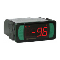
| Category | Controller |
| Model | TC-900e 2HP |
| Brand | Full Gauge |
| Power Supply | 115 or 230 Vac ±10% (50/60 Hz) |
| Operating Temperature | 0 to 50 °C |
| Measurement Range | -50 to 105 °C |
| Operating Humidity | 10 to 90% RH (non-condensing) |
Wiring diagrams for 115 Vac and 230 Vac connections, detailing sensor and power inputs.
Guide to accessing and navigating the quick access menu using controller keys.
Description of shortcut functions assigned to controller keys for temperature display.
Core operational procedures for the controller.
Accessing advanced functions and configuring controller parameters.
Details on the access code required for parameter configuration.
Setting the hysteresis for normal operation.
Adjusting the ambient temperature sensor reading for accuracy.
Defining the minimum and maximum setpoint values allowed for user adjustment.
Configuring the initial delay before the controller starts operations.
Setting the shortest allowed time between consecutive defrost cycles.
Determining the maximum time the cooling output remains active.
Setting the time interval between the start of one defrost and the next.
Maximum time allowed for the defrost process to complete.
Configuring how the defrost cycle is initiated (manual, time, or sensor-based).
Setting the evaporator temperature threshold to end the defrost cycle.
Setting the absolute maximum time allowed for a defrost cycle.
Determining how the defrost cycle concludes (temperature or time).
Enabling or disabling the fan operation during defrost cycles.
Setting the duration for the drainage phase after defrost.
Setting the evaporator temperature for the fan to return to normal operation.
Maximum time the fan stays off after defrost before resuming operation.
Configuring fan operation during cooling, defrost, and idle states.
Duration for gas injection during defrost cycles.
Time the door must remain closed to activate economic setpoint.
Difference between S3 and S1 to deactivate economic setpoint.
Difference between S3 and S1 to activate economic setpoint.
Maximum duration the economic setpoint can remain active.
Maximum time the fast freezing function can remain active.
Control of fan operation status (on/off) during cyclic mode.
Control of compressor operation status (on/off) during cyclic mode.
Setting the minimum time the compressor remains off between cycles.
Maximum time the compressor is allowed to remain off.
Setting the minimum time the compressor remains on during cycles.
Maximum time the compressor is allowed to remain on.
Maximum duration the door can remain open before triggering an alarm.
Enabling or disabling the control functions shutdown feature.
Configuring the fan to stop when a high condenser temperature is detected.
Setting the condenser temperature threshold for specific fan operations.
Time allowed for the condenser to cool down after a high temperature event.
Setting the time the condenser fan operates after compressor shutdown.
Delay time for the fan operation after compressor start.
Configuring fan control logic based on evaporator temperature.
Configuration of the first digital input for various functions.
Configuration of the second digital input for various functions.
Compensating for deviations in the evaporator temperature sensor (S2) reading.
Compensating for deviations in the S3 temperature sensor reading.
Authorizing or disabling the shutdown of control functions.
Enabling and configuring the function lock mode for security.
Setting the time in seconds for the controller to automatically activate the function lock.
List of error codes and their meanings for sensor failures or range issues.
Codes indicating operational status like economic setpoint, open door, or control functions.
Indicators for high/low ambient temperature, condenser temperature, and compressor limits.
Signals for control routines being off or defrost completion issues.
Accessory for storing and loading controller parameters via USB or TTL connection.
Protective cover to prevent water ingress and protect the instrument during washing.
Frame for easier installation and customization, including optional switches.
Information on recyclable packaging materials and proper disposal of electronic waste.
Details on the 2-year warranty against manufacturing defects.
Conditions that void the product warranty, including improper use or damage.
Specific events and actions that will cause the product warranty to be forfeited.
Procedure for claiming warranty service and requirements for technical support.