FCO770 Users Guide Issue 1 Page 83
C
C
o
o
n
n
f
f
i
i
g
g
u
u
r
r
i
i
n
n
g
g
f
f
o
o
r
r
a
a
D
D
u
u
m
m
p
p
T
T
e
e
s
s
t
t
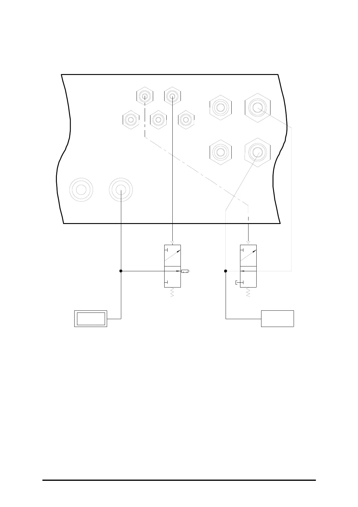
TEST CHAMBER
TEST ITEM
DUMP
VOLUME
4mm O/D
V1
V2 = CHANGE OVER VALVE
V1 = VENT VALVE
V2
-+
TEST
Pneumatic Outputs
P1 (Jig) P2 (Vent)
P3 P4 P5
AIR
SUPPLY
MIN. 5B A R
MAX. 10BAR
REGULATOR
SUPPLY
REGULATED
AIR IN
REGULATED
AIR OUT
• Ideally, the dump volume should be equal to the test volume.
• If a reference volume is used it must be vented to atmosphere after each test.
• Keep the effective volume of the jig with the test item in place to a minimum.
• The diagram above shows the conventional dump test method with the Jig output
controlling V2. An alternative method uses the prefill output to operate V2. This
arrangement refills the dump volume during the vent time and so may achieve a faster
test in some cases. This method is also necessary for vacuum dump tests using air-
saving since the reference volume can not be charged at standby. Pneumatic output P1
can be reprogrammed for use as the prefill output if required. Note that the sense of
the prefill output is reversed compared to the jig output. This can be overcome by
swapping the ports of V2, or using the Combo function to invert the sense of the
prefill signal.
 Loading...