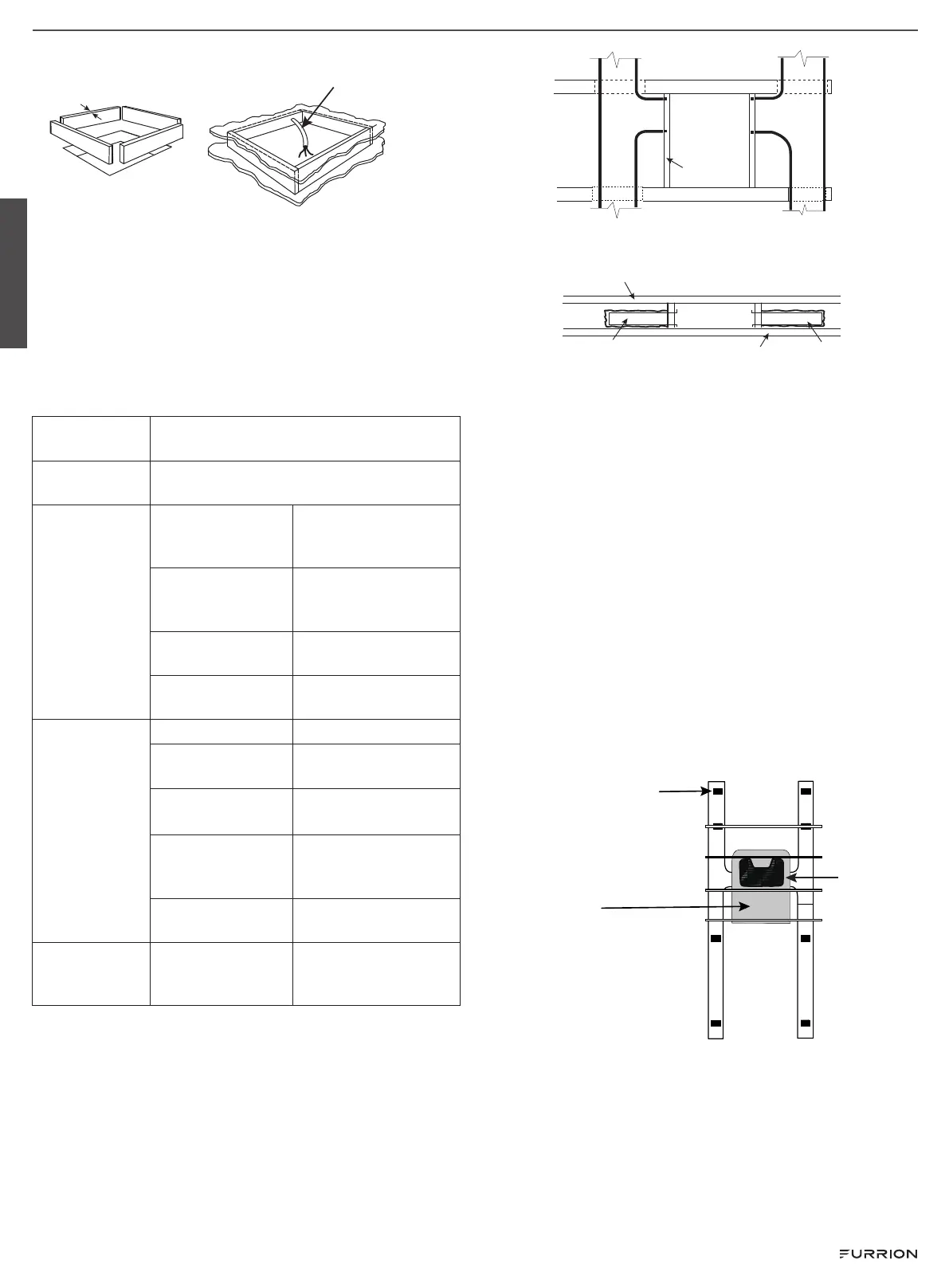
Do not cut
roof structure
or rafters
Good: rafters
supported by
cross beams
Good: location
between roof
rafters
¾" Min.
(19.05 mm)
Leave access for
power supply wiring
Air Distribution Duct Sizing and Design
The installer of this system must design the air distribution
system for their particular application.
NOTE: Make sure ductwork will NOT bend or collapse during
and after installation, and that it is correctly insulated and
sealed. Otherwise, damage to roof structure and ceiling could
occur.
The following requirements must be met for properly operate
the unit:
Roof Cavity
Depth
3.5"-6" (89mm-152mm)
Duct Cross
Sectional Area
21 Sq. In. Min.
Duct Size
Depth
1½ " Min. - 2½ " Max.
(38mm Min. - 63.5mm
Max.)
Width
7" Min. - 10" Max.
(178mm Min. - 254mm
Max.)
Total Duct Length
15Ft. Min. - 40Ft. Max.
(4.5m - 13m)
Duct Length (short
run)
1/3 Total Duct Length
Register
Requirements
per A/C Unit
Number Required 4 Min. - 8 Max.
Supply Register
Free Air Area
14 Sq. In. (90 sq. cm)
Return Register
Free Air Area
40 Sq. In. (258 sq. cm)
Distance From
Duct End
5" Min. - 8" Max.
(127mm Min. - 203mm
Max.)
Distance From
Elbow
15" (381mm)
Total System
Static Air
Pressure
Blower at High
Speed, Filter &
Grille In Place
0.55 - 1.10 In. W.C.
● Properly insulate and seal all discharge air ducts to prevent
condensation from forming on their surfaces or adjacent
surfaces during operation of the unit. This insulation must
be R-7 minimum.
Frame
Duct
Duct
Frame
Frame
Roof
Opening
Roof Opening
Roof
Duct
Ceiling
Duct
TOP VIEW (BACK OF RV)
SIDE VIEW (TOWARD BACK OF RV)
● Return air openings must have 80 square inches (516
square centimeters) minimum free area including the filter.
● Return air to the unit must be filtered to prevent dirt
accumulation on the unit cooling surface.
Air Distribution System Installation
It is the responsibility of the installer to review each RV floor
plan to determine the following items in conjunction with “Air
Distribution Duct Sizing and Design” section
NOTE: Alternate configurations and methods may be used
which will allow the unit to operate properly, however, these
alternate configurations and methods MUST be approved by
Furrion in writing.
● Duct size
● Duct layout
● Register size
● Register location
● Thermostat location
● Indoor temperature sensor location (if applicable)
Front
Registers 4 Min - 8 Max.
(Per Unit) 14 Sq. In.
Free Area Per Register
Air Conditioner
Return Air
Preparing Wire Connections
Each rooftop air conditioner opening must be prepared
with proper wiring to connect the ceiling controller of the air
conditioner to the 115VAC and 12VDC supply voltage, wall
thermostat and furnace switch.
NOTE: The wire connections need to be positioned in the
forward facing 1/4 section of the opening.
English
CCD-0007273 Rev: 11-04-22
- 5 -
 Loading...